


Page 24 (52)
Ver 2_en_2022-06-27
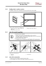
Assembly Instructions
Envistar Flex
ivprodukt.docfactory.com
Order Portal
support drawing is available at
IV Produkt’s order portal
(Technical data). See
"1.1 Intended
use”, page 6.
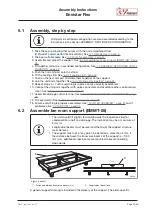
1. Screw the lock nut (1) onto the support foot (2) and make sure it is slightly screwed in.
00004
40—50 mm
20—40 mm
1
2
2. Screw all feet into the threaded holes in each angle profile.
3. Push in and locate, in the track of the profile, the screws that will later be used to tighten
the corner stays. Make sure you have the right number (2 per corner stay).
4. Screw the angle profiles and support legs together.
5. Use a spirit level and ensure that the longitudinal beam of the unit is level.
6. Adjust the height and inclination of the support by screwing the support feet.
7. Secure all feet with the lock nuts.
6.3
Fit sealing strip
• The sealing strip is only fitted on one of two opposite parts.
• The sealing strip is not fitted on the rotary heat exchanger.
• For units in sectioned configuration, sealing strip must also be fitted in
the division. Does not apply to ThermoCooler HP/EcoCooler.
• For outdoor version units, sealing strip must also be fitted in the outer
edge, see
"6.3.1 Sealing strip in outdoor version”, page 25
.
• See also
"7 ASSEMBLY, SECTIONED CONFIGURATION”, page 30.
3 mm
2
3
1
4
00052
Figure: Sealing strips, location.
1. Sealing strip of type D-profile
2. Sealing strip in corner
3. Sealing strip joint
4. Profile in cross section
1. Divide the strip into two.
2. Fit the strip in the middle surfaces of the unit, about 3 mm from the inner edge. Remove
the protective layer over the adhesive, after which the strip is glued on. Bend the strip in
the corners and join it on vertical sides.