


1
ENGLISH
ENGLISH
The thermistor eventually requested has to be connected following
diagram in fig.26 page 89.
The CDX/IMX/VMX type G electric vibrators are not equipped with
neither thermal protection nor PTC thermistor.
The terminals of the thermal protector (or thermistor) are also housed
in the terminal box and are marked P1 and P2.
On customer request the electric vibrator can be equipped with a 26W anti-
condensation heater; the heater can be recommended in case of ambient
temperature lower than -20°C and intermittent duty in high humidity ambients,
to avoid condensation inside the unit. For electrical connection of the heater
see diagram in page 90.
3.3 TERMINAL BOARD WIRING DIAGRAMS
ATTENTION: A tropicalised screw, indicated with the earth symbol, is
situated in the terminal box and on the external surface (fig.8 page 6).
The yellow-green (only green in the U.S.A.) conductor of the power
supply cable must be connected to this screw which acts as a earth
connector for the vibrator.
The wiring diagrams is on the bottom side of the terminal box cover, and is
also indicated in page 86.
3.4 FIXING OF THE POWER SUPPLY CABLE TO THE
VIBRATOR TERMINAL BOARD
The electric vibrators are supplied without cable gland.
The user has to mount a cable gland in compliance with the Laws and
Standards, for the specific zone of use and for the country of installation
and use.
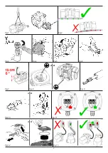
Always use eyelet terminal for connections (Fig. 9, page 6).
Prevent progressive disintegration that could cause interruption or
short circuits (A Fig.10, page 6).
Remember to place the relevant washers before the nuts (B Fig.10,
pag.6). This prevents loosening with consequent uncertain connection
to the network and possible damage.
Do not overlay the individual cable wires (Fig.11, page 6).
Carry out the connection according to the diagrams shown and tighten the
cable-holder fully home (A Fig. 12, page 6).
Position the foam rubber block ensuring that all wires are held and assemble
the cover paying attention not to damage the seals (B Fig. 12, page 6).
Always check that the network voltage and frequency correspond to
that indicated on the vibrator’s identification plate before supplying
power (Fig. 14, page 7).
All vibrators must be connected to an adequate external overloading
protection, according to the regulations in force.
When
vibrators
are installed
in pairs
it is important that each one has its
own external overloading protection and that these protections are interlocked
together. This is because if a vibrator accidentally shuts down, the power
supply is interrupted to both vibrators at the same time, so as not to damage
the equipment to which they are applied (Fig. 13, page 6).
See fig. 25, page 88 as example of power and control circuits in the case
of vibrators with thermostat.
See fig. 26, page 89 as example of power and control circuits in the case
of vibrators with thermistor.
Important!: For the choice of start-up/shutdown and overloading
protection electrical appliances refer to the technical data, electrical
features, nominal current and start-up current. Also always choose
delayed magnetic-circuit breakers, to prevent release during start-up
time, which may be longer in low environmental temperatures.
3.5 VARIABLE FREQUENCY SUPPLY
All of the vibrators can be powered with a frequency drive (inverter) from
20Hz up to the nominal frequency, with constant torque functioning (rather
with linear course of the Volt-Hertz curve) using a PWM (Pulse Width Mo-
dulation) frequency drive.
When a variable frequency inverter is used, do not exceed the max fre-
quency admitted. In case of doubts about the calculation of the centrifugal
force (CF) at a certain speed (S) please contact Italvibras. General formula
to be applied:
CF
2
= (S
2
/S
1
)
2
*
CF
1
SECTION 4 –
Use of the vibrator
4.0 PRELIMINARY CHECKS
ATTENTION: Controls must be carried out by specialized staff. During
disassembly and re-assembly of protective parts (terminal box cover
and weight cover), remove the power supply from the vibrator
Check current draw.
- Remove the cover from the terminal board compartment.
- Power the vibrator.
- Use an amperometer to verify (Fig.15, page 7), on each phase, that the
input current does not exceed the value indicated on the identification
plate.
If the current draw exceeds that stated on the plate:
- Check the flexible system and the vibrating machine framework are in
compliance with the regulations for correct application.
- Reduce force (centrifugal force) by adjusting the weights. Reduce them
until the value of absorbed current corresponds to that stated on the
identification plate.
ATTENTION: Avoid touching or allowing anyone to touch live parts
such as the terminal board.
Remember to allow the vibrators to function for brief periods of time
during set-up. This prevents damage to the vibrator and structure in
the case of anomalies.
Once the indicated controls have been carried out close the cover
definitively.
Check direction of rotation:
In applications where direction of rotation must be ascertained (Fig. 16,
page 7):
- Remove a weight cover;
- Wear protective glasses;
- Power the vibrator for a brief period of time;
ATTENTION: in this phase ensure that no-one can touch or be struck
by the rotating weights.
- If the direction of rotation must be inverted, act on terminal board connec-
tions, after having removed the power supply from the vibrator, reversing
two phases.
- Reposition the covers, ensuring that the seals (OR) are correctly positioned
and tighten the screw fastener.
4.1 VIBRATION FORCE ADJUSTMENT
ATTENTION: This operation must be carried out exclusively by spe-
cialized staff with the power supply disconnected.
- To adjust vibration intensity it’s necessary to remove the weight covers.
- It is usually necessary to adjust the weights in the same direction in the
two ends (Fig.17, page 7). To allow exact adjustment of the weights, the
vibrators are equipped with a patented system that prevents the adjustable
weight to turn in the wrong direction (Fig.18, page 7).
Summary of Contents for CDX IMX VMX Series
Page 4: ...1 2 4 5 D B C A 3 D 1 2 5 CDX G 4 35 40 50 CDX G D 3 35 40 50 60 70 80...
Page 6: ...Fig 1 Fig 2 Fig 3 Fig 4 Fig 5 Fig 6 Fig 7 Fig 8 A B Fig 10 Fig 11 A B A B Fig 12 Fig 13 Fig 9...
Page 7: ...Fig 14 A C B Fig 15 Fig 16 Fig 17 Fig 18 Fig 19 Fig 20 Fig 21...
Page 8: ...NOTE Fig 22...
Page 9: ...NOTE...
Page 82: ...82...