background image


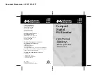
Quick Start Guide 

Dual Measurement Multimeter 


IDM-8341/8342 Series 
 

EN


Summary of Contents for IDM-8341 Series

Page 1: ...Quick Start Guide Dual Measurement Multimeter IDM 8341 8342 Series EN...

Page 2: ...e RS Components shall not be liable for loss of use of the instrument or other incidental or consequential damages expenses or economic loss or for any claim or claims for such damage expense or econo...

Page 3: ...this manual or on the instrument WARNING Warning Identifies conditions or practices that could result in injury or loss of life CAUTION Caution Identifies conditions or practices that could result in...

Page 4: ...m measurement at the source of a low voltage installation or at building installations Note below Do not disassemble the instrument unless you are qualified as service personnel Make sure that the COM...

Page 5: ...of a fuse blowout is fixed before fuse replacement Cleaning the Instrument Disconnect the power cord before cleaning Use a soft cloth dampened in a solution of mild detergent and water Do not spray a...

Page 6: ...which becomes conductive due to condensation which is expected In such conditions equipment is normally protected against exposure to direct sunlight precipitation and full wind pressure but neither t...

Page 7: ...ed to the terminal which is marked with the letter N or coloured Blue or Black The wire which is coloured Brown must be connected to the terminal marked with the letter L or P or coloured Brown or Red...

Page 8: ...get started quickly For more details such as setup procedure parameters remote control commands optional scanner digital I O and specifications refer to the user manual Conventions press the ACV key...

Page 9: ...BASIC MEASUREMENT AC Voltage Range 0 to 750V Connection Activation Auto range setting Manual range setting...

Page 10: ...DC Voltage Range 0 to 1000V Connection Activation Auto range setting Manual range setting...

Page 11: ...AC DC Voltage Range 0 to 1000V Connection Activation Auto range setting Manual range setting...

Page 12: ...AC Current Range 0 to 0 5A or 0 to 12A Connection Activation Auto range setting Manual range setting...

Page 13: ...DC Current Range 0 to 2A Connection Activation Auto range setting Manual range setting...

Page 14: ...AC DC Current Range 0 to 2A Connection Activation Auto range setting Manual range setting...

Page 15: ...Resistance Range 0 to 50M Connection Activation Auto range setting Manual range setting Diode Range N A Connection Activation...

Page 16: ...Capacitance Range 5nF to 50uF Connection Activation 2X Continuity Threshold 5 Connection Activation 2X...

Page 17: ...Frequency Period Measurement Range 10Hz 1MHz Connection Activation Period Measurement Range 1 0 s 100ms Connection Activation 2X...

Page 18: ...Temperature Range Thermocouple 200 C 300 C Connection Activation...

Page 19: ...ACV DCV ACA DCA Resistance Diode Capacitance Frequency Period and Continuity Before an advanced measurement can be made a basic measurement function must first be selected Combination with Basic Meas...

Page 20: ...dBm W Available in Activation Reference impedance setting dB Available in or Activation Change voltage range...

Page 21: ...Max Applicable in Activation Min Applicable in Activation x 2...

Page 22: ...Relative Available in Activation Reference value setting Measured value when activated is the reference value Hold Available in Activation...

Page 23: ...eys to navigate to the digit to be edited or to select the decimal point Use the Up and Down arrow keys to edit the selected digit or to place the position of the decimal point 2 Confirm high setting...

Page 24: ...4 Confirm low setting...

Page 25: ...e grounded to ensure accuracy All specifications are applicable to the main 1 st display only General Specifications Specification Conditions Temperature 23 C 5 C Humidity 80 RH 75 RH for resistance m...

Page 26: ...Ratio 90 dB at dc 50 or 60Hz 0 1 1k unbalanced slow rates DC Current Range Resolution Full Scale Accuracy 1 year 23 C 5 C Shunt Resistance Burden Voltage 500 A 10nA 510 00 0 05 5 100 0 06V max 5mA 10...

Page 27: ...es the AC component of the input with up to 400Vdc of bias on any range AC Common Mode Rejection Ratio 60 dB at dc 50 or 60Hz 0 1 1k unbalanced slow rates Input impedance 1M 2 in parallel with 100pF A...

Page 28: ...e error by 0 2 2 When measuring resistances greater than 500k please use shielded test leads to eliminate the noise interference that may be induced by standard test leads Open circuit voltage approxi...

Page 29: ...ut is greater than 10 of the range 2 Need to use the REL function Input protection of 500V peak on all ranges Frequency Measurement Range Accuracy 1 year 23 C 5 C 10Hz 500Hz 0 01 5 500Hz 500kHz 0 01 3...

Page 30: ...A 50mA 2 5mA 500mA 25mA 5 A 0 25A 2kHz 10 A 2 5A 2kHz Temperature Specifications Sensor Type Measurement Range Resolution Accuracy 1 year 23 C 5 C Thermocouple J 200 300 C 0 1 C 2 C K T Note The tempe...

Page 31: ...were applied EMC EN 61326 1 EN 61326 2 1 Electrical equipment for measurement control and laboratory use EMC requirements 2013 Conducted Radiated Emission EN 55011 2009 A1 2010 Electrostatic Discharg...

Page 32: ...h PO Box 99 Corby Northamptonshire NN17 9RS United Kingdom Japan West Tower 12th Floor Yokohama Business Park 134 Godocho Hodogaya Yokohama Kanagawa 240 0005 Japan USA 7410 Pebble Drive Fort Worth Tex...

Reviews: