
89
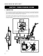
CHAPTER 7. POWER STEERING SYSTEM
2.
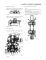
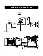
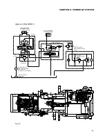
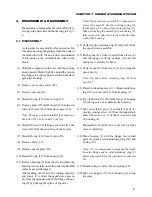
WORKING PRINCIPLE
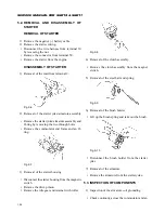
The orbit roll has 5 ports as shown in Fig. 7-2.
Port EF is connected to another actuator circuit.
P
T
R
L
Suction filter
Engine
Pump
Return filter
Main relief
vlave
To another
actuator circuit
G-rotor
Steering
column
Steering
wheel
Spool
sleeve
R
L
T
P
EF
T
P
R
L
EF
Emergency
actuator
Steering cylinder
Mini-orbit roll
E
To another
actuator circuit
T
P
R
L
EF
E
To another
actuator circuit
T
P
R
L
EF
E
Fig. 7-2
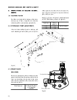
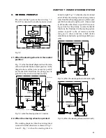
2.1. When the steering wheel is in the neutral
position:
Fig. 7-3 is the functional diagram when the mini-
orbit roll is shifted in the neutral position. As the
diagarm shows all the ports except for port EF
are blocked. All fluid from the pump goes via
port EF to the circuit of another acutator.
Fig. 7-3: when the steering wheel is in neutral
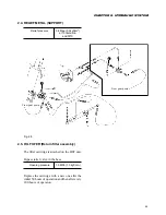
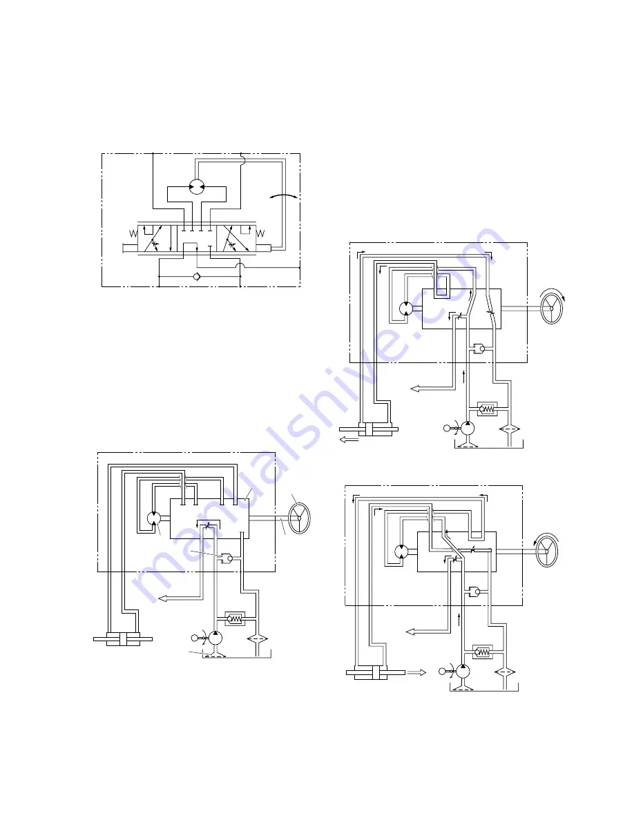
2.2. When the steering wheel is operated:
The working diagrams when the steering wheel
is turned in either direction are shown in Fig. 7-
4 and 5: Fig. 7-4 when the steering wheel is
turned to right; Fig. 7-5 when the wheel is turned
to left. While the steering wheel is being turned,
some fluid from the pump goes to a cylinder port:
port R when turned to right; port L when turned
to left and the other flows to port EF. The steer-
ing system has the priority to other hydraulic
functions, the fluid used in the steering system
returns via port T to the oil reservoir, and the
rest goes to other actuators, which makes
sumultaneous hydraulic operation partially pos-
sible.
Fig. 7-4 (When the steering wheel is turned to right)
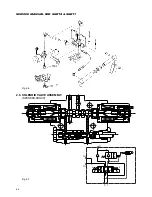
Fig. 7-5 (When the steering wheel is turned to left)
Summary of Contents for SCM49
Page 1: ...S E R V I C E M A N U A L I S E K I L A W N M O W E R S LAWN MOWERS MOWER DECKS SCM48 SCM54 ...
Page 7: ...7 CHAPTER 1 INTRODUCTION 3 EXTERIOR VIEW AND DIMENSIONS 1935 mm 1965 mm 1100 mm 1265 mm ...
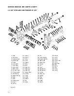
Page 36: ...36 SERVICE MANUAL FOR SGR19 SGR17 Fig 3 55 III 3 CYLINDER BLOCK 1 EXPLODED VIEWS ...