
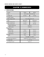

111
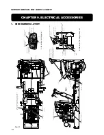
CHAPTER 9. ELECTRICAL ACCESSORIES
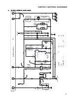
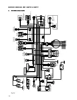
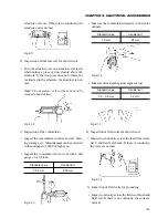
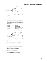
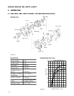
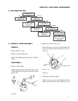
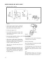
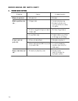
6.2. TROUBLESHOOTING
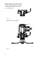
Fig. 9-38
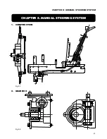
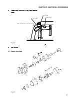
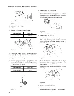
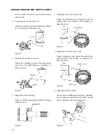
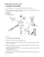
6.3. REMOVAL AND DISASSEMBLY
REMOVAL
• Remove battery wiring.
• Remove the fan and fan belt.
• Remove the tightening bolts and remove the gen-
erator.
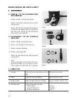
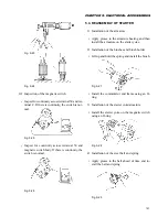
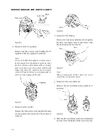
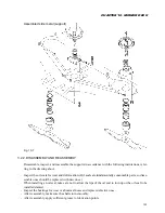
DISASSEMBLY
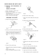
a. Removal of the pulley
Hold the hexagonal part of the shaft with a socket
wrench and remove the pulley nut with an open
end wrench.
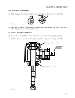
b. Removal of the rear end cover
Remove the three rear end cover tightening bolts
and nut for terminal B. Then the rear cover is
removed.
Fig. 9-39
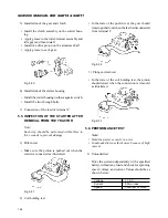
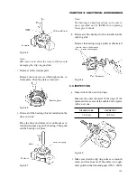
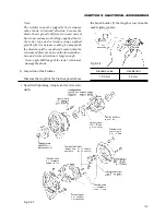
c. Removal of the brush holder
Remove the two screws which tighten the brush
holder and rectifier. Then the brush is removed.
Check fan belt.
Replace belt.
GOOD
Check diode.
NG
NG
Replace diode
assembly.
GOOD
Check stator.
NG
Replace stator
assembly.
GOOD
Check brushes.
NG
Replace brush
assembly.
GOOD
Check IC regulator.
Replace regulator
assembly.
Summary of Contents for SCM49
Page 1: ...S E R V I C E M A N U A L I S E K I L A W N M O W E R S LAWN MOWERS MOWER DECKS SCM48 SCM54 ...
Page 7: ...7 CHAPTER 1 INTRODUCTION 3 EXTERIOR VIEW AND DIMENSIONS 1935 mm 1965 mm 1100 mm 1265 mm ...
Page 36: ...36 SERVICE MANUAL FOR SGR19 SGR17 Fig 3 55 III 3 CYLINDER BLOCK 1 EXPLODED VIEWS ...