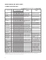


22
SERVICE MANUAL FOR SGR19 & SGR17
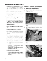
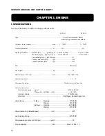
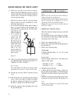
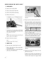
Specified deflection
5 – 10 mm
Fig. 3-4
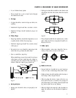
• Adjustment:
When the deflection is more than specified, ten-
sion the belt properly by moving the alternator.
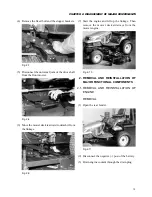
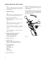
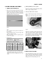
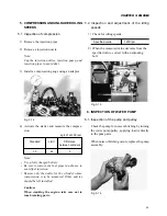
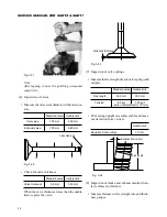
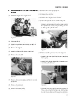
3. INSPECTION AND ADJUSTMENT OF
VALVE CLEARANCES
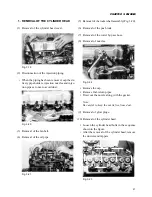
3.1. Remove the cylinder head cover.
3.2. Turn the crankshaft by hand so that the piston in
No.1 cylinder reaches at TDC: align the
TDC notch in the crankshaft pulley with the pro-
jection on the gear case.
Direction
of rotation
TDC
Injection
timing
Crankshaft
pulley
Fig. 3-5
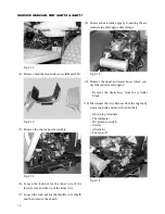
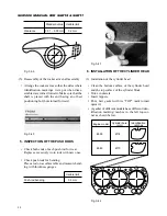
Note:
When it is difficult to distinguish between TDC
in compression stroke and TDC in exhaust stroke,
use height difference among the push rods as a
criterion for judgement. When the heights of the
push rods (No.1, 2,3, and 6 viewed from the fan)
are about 5 mm lower than those of No.4 and 5,
the piston in No. 1 cylinder is at TDC in com-
pression stroke.
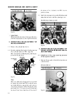
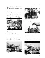
3.3. Insert a feeler gauge of a specified thickness and
adjust the clearance with the adjusting screw.
Specified valve clearance (cold):
Intake
0.25 mm
Exhaust
0.25 mm
Fig. 3-6
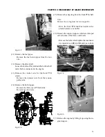
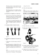
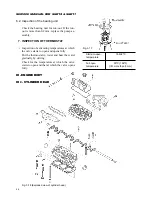
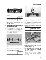
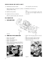
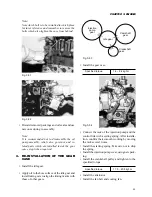
4. INSPECTION AND ADJUSTMENT OF
NOZZLE OPENING PRESSURE AND IN-
JECTION TIMING
4.1. Adjustment of the valve opening pressure
of the injection nozzles
• Measure the pressure of initial fuel injection on
a nozzle tester.
E393-G & E383-G:
Specified pressure
120 kg/cm
2
Fig. 3-9
Summary of Contents for SCM49
Page 1: ...S E R V I C E M A N U A L I S E K I L A W N M O W E R S LAWN MOWERS MOWER DECKS SCM48 SCM54 ...
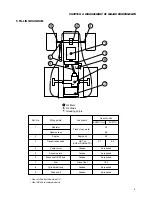
Page 7: ...7 CHAPTER 1 INTRODUCTION 3 EXTERIOR VIEW AND DIMENSIONS 1935 mm 1965 mm 1100 mm 1265 mm ...
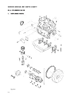
Page 36: ...36 SERVICE MANUAL FOR SGR19 SGR17 Fig 3 55 III 3 CYLINDER BLOCK 1 EXPLODED VIEWS ...