


55
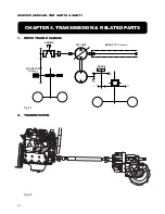
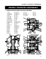
CHAPTER 4. TRANSMISSION & RELATED PARTS
Fig. 4-9
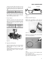
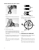
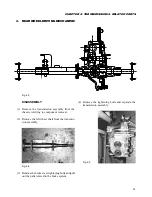
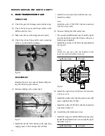
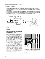
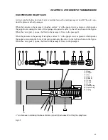
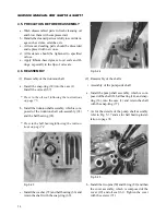
(5) Adjustment of drive pinion backlash
Adjust the backlash between the drive pinion and
the ring gear by shimming.
Fig. 4-10
Fig. 4-11
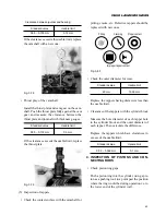
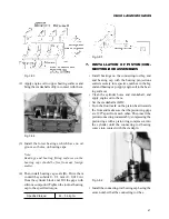
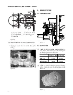
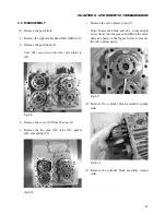
a. Measuring tools
• Holder of drive pinion set
• Dial guage setting tool
Fig. 4-12
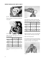
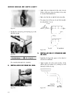
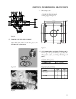
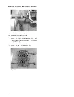
b. If the measurement is deviates from the speci-
fied range at the point 150 mm apart from the
drive pinion center, correct by shimming at A
and B.
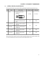
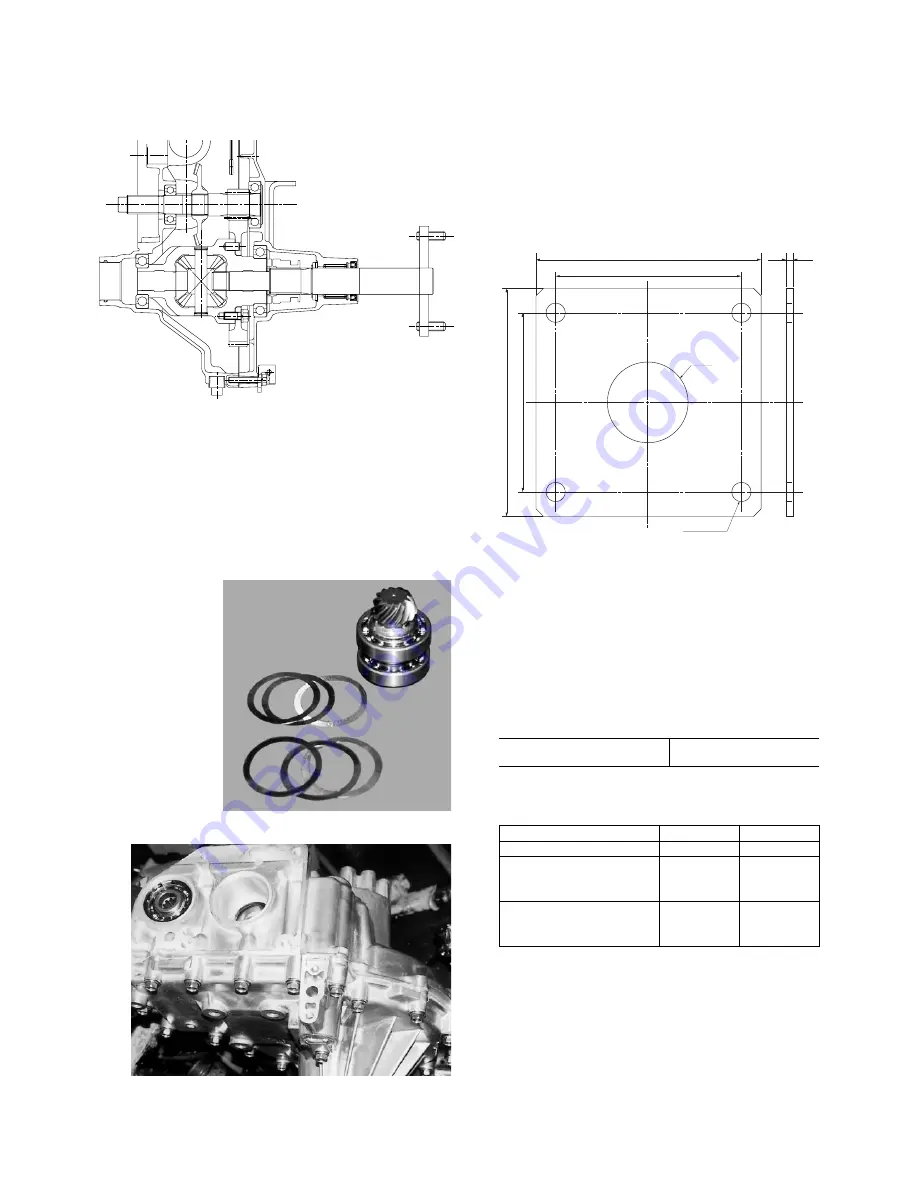
Backlash of drive pinion
Standard value
0.1 – 0.3 mm
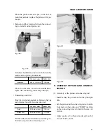
Required number of shims
Side A
Side B
Standard
3
3
To extend
4
2
5
1
6
0
To close
2
4
1
5
0
6
135
106
112
135
4.5
φ
48
4 –
φ
11
unit: mm
Summary of Contents for SCM49
Page 1: ...S E R V I C E M A N U A L I S E K I L A W N M O W E R S LAWN MOWERS MOWER DECKS SCM48 SCM54 ...
Page 7: ...7 CHAPTER 1 INTRODUCTION 3 EXTERIOR VIEW AND DIMENSIONS 1935 mm 1965 mm 1100 mm 1265 mm ...
Page 36: ...36 SERVICE MANUAL FOR SGR19 SGR17 Fig 3 55 III 3 CYLINDER BLOCK 1 EXPLODED VIEWS ...