


49
ISEKI LAWN MOWERS
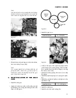
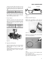
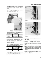
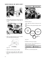
Temporarily tighten the flywheel.
Chock the flywheel, and then tighten the bolts
to the specified torque.
Specified torque
9.5 kgf·m
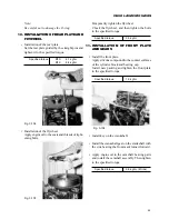
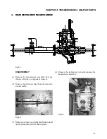
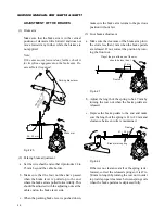
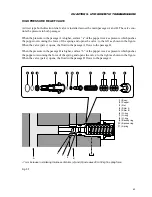
11. INSTALLATION OF FRONT PLATE
AND GEARS
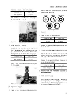
• Install the front plate.
Apply silicone compound to the contact surfaces
of the cylinder block and bearing cap.
Install new packing and tighten the front plate
to the specified torque.
Specified torque
1.9 kgf·m
Note:
Be careful not to damage the O-ring.
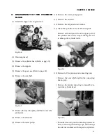
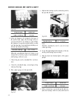
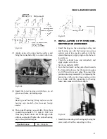
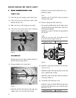
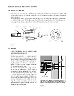
10. INSTALLATION OF REAR PLATE AND
FLYWHEEL
• Installation of the rear plate
Set the rear plate guided by the straight pins and
tighten it to the specified torque.
Specified torque
M10:
4.1 kgf·m
M12:
8.4 kgf·m
Fig. 3-102
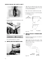
• Installation of the flywheel
Apply engine oil to the seats and threads of tight-
ening bolts.
Fig. 3-103
Fig. 3-104
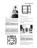
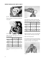
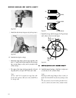
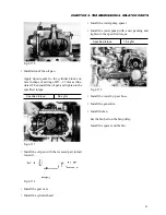
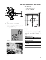
• Install key on the crankshaft.
• Install the crankshaft gear on the crankshaft with
the side bearing the front mark turned forward.
• Apply engine oil to the camshaft bearing parts
and install the camshaft assembly. Then tighten
to the specified torque.
Specified torque
0.8 kgf·m (6 ft·lbs)
Summary of Contents for SCM49
Page 1: ...S E R V I C E M A N U A L I S E K I L A W N M O W E R S LAWN MOWERS MOWER DECKS SCM48 SCM54 ...
Page 7: ...7 CHAPTER 1 INTRODUCTION 3 EXTERIOR VIEW AND DIMENSIONS 1935 mm 1965 mm 1100 mm 1265 mm ...
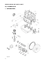
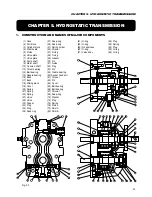
Page 36: ...36 SERVICE MANUAL FOR SGR19 SGR17 Fig 3 55 III 3 CYLINDER BLOCK 1 EXPLODED VIEWS ...