


73
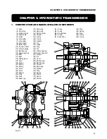
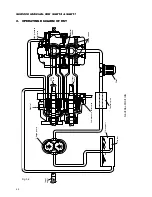
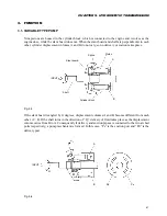
CHAPTER 5. HYDROSTATIC TRANSMISSION
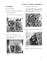
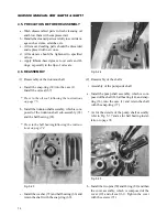
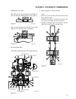
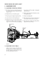
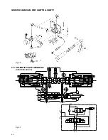
e. After being reassembled, make sure that the
shafts (8 & 9) turn smoothly using an adjustable
end wrench.
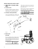
b. Install the valve sub-assembly (28).
Apply grease to the valve ahead of time to pre-
vent it from falling.
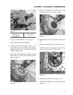
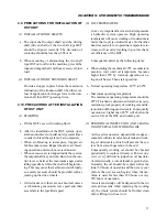
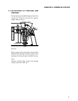
c. Install the springs (22), pins (50), and gasket (49)
onto the case.
Apply grease to the springs ahead of time in or-
der to prevent them from falling.
Fig. 5-34
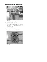
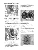
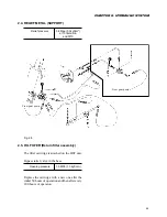
d. Install the port block assembly onto the case and
tighten the eight socket-head bolts (50).
Tightening torque of
49.0
±
5 N·m
socket-head bolt (50)
Fig. 5-35
Fig. 5-36
Fig. 5-37
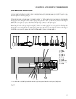
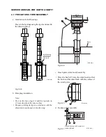
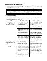
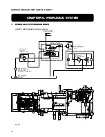
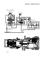
8
9
14
36
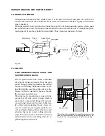
Pressed in
Pump shaft assembly
Motor shaft assembly
(Unit: mm)
Summary of Contents for SCM49
Page 1: ...S E R V I C E M A N U A L I S E K I L A W N M O W E R S LAWN MOWERS MOWER DECKS SCM48 SCM54 ...
Page 7: ...7 CHAPTER 1 INTRODUCTION 3 EXTERIOR VIEW AND DIMENSIONS 1935 mm 1965 mm 1100 mm 1265 mm ...
Page 36: ...36 SERVICE MANUAL FOR SGR19 SGR17 Fig 3 55 III 3 CYLINDER BLOCK 1 EXPLODED VIEWS ...