background image

37

NOTE: DIAGRAMS & ILLUSTRATIONS ARE NOT TO SCALE.

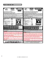
SAFETY / LISTING LABEL - MPI27CD


Madison Park™ 27 CD

MANUFACTURED BY:

INNOVATIVE HEARTH PRODUCTS

1502 14TH ST NW

AUBURN, WA., USA 98001


MPI27CD

SERIAL

 NO.

VENTED GAS FIREPLACE HEATER - NOT FOR USE WITH SOLID FUEL

CONFORMS TO ANSI Z21.88-2014/CSA 2.33-2014 AND CAN/CGA-2.17-M91 (R2009).

THIS APPLIANCE MUST BE INSTALLED IN ACCORDANCE WITH LOCAL CODES, IF ANY.  IF NOT, FOLLOW THE CURRENT ANSI Z223.1/NFPA 

54-LATEST EDITION (USA) OR CAN/CGA  B149.1-LATEST EDITION (CANADA). THIS APPLIANCE MUST BE INSTALLED IN ACCORDANCE 

WITH THE MANUFACTURER’S INSTALLATION INSTRUCTION. FOR INSTALLATION IN SOLID FUEL BURNING FIREPLACES ONLY - MASONRY 

OR FACTORY BUILT.  THIS VENTED GAS FIREPLACE HEATER IS NOT FOR USE WITH AIR FILTERS. 
THIS APPLIANCE IS ONLY FOR USE WITH THE TYPE OF GAS INDICATED ON THE RATING PLATE AND MAY BE INSTALLED IN AN 

AFTERMARKET, PERMANENTLY LOCATED, MANUFACTURED (MOBILE) HOME WHERE NOT PROHIBITED BY LOCAL CODES. SEE OWNER’S 

MANUAL FOR DETAILS. THIS APPLIANCE IS NOT CONVERTIBLE FOR USE WITH OTHER GASES UNLESS A CERTIFIED KIT IS USED.
DANGER: RISK OF ELECTRICAL SHOCK. DISCONNECT POWER BEFORE SERVICING UNIT.

IF ELECTRICALLY CONNECTED, CONNECTIONS AND GROUNDING MUST BE IN ACCORDANCE WITH LOCAL CODES, IF ANY. IF NOT, 

FOLLOW THE CURRENT NATIONAL ELECTRICAL CODE ANSI/NFPA 70-LATEST EDITION (USA) OR CSA C22.1-LATEST EDITION (CANADA).

FACTORY EQUIPPED FOR NATURAL GAS. IF CONTROL PANEL 

CONTRADICTS THIS LABEL, UNIT FUEL TYPE HAS BEEN CONVERTED.

RATINGS

Madison Park 27 CD (MPI27CD)

For use only with barrier Part 

No. J4343. Follow installation 

instructions.

NATURAL GAS

LP GAS

MAX/MIN INPUT BTUH 0-2,000 FT (0-610 M)*

30,000 / 21,000

25,000 / 20,000

MANIFOLD PRESSURE (IN. WC)

3.5

10.0

MIN. INLET PRESSURE (IN. WC)

5.0

10.5

ORIFICE (DMS) 0-2,000 FT (0-610 M)*

#38

#53

*UNIT FACTORY EQUIPPED FOR 0-2000 FT/0-610 M, IN CANADA 0-4500 FT/0-1370 M. ELECTRICAL RATING: 120 VAC, 60 HZ, LESS THAN 2 AMPS

CHIMNEY - USE 3" (76 MM) GAS VENT FLEX CHIMNEY LINER LISTED TO UL 1777 OR ULC S635.  

THIS APPLIANCE MUST BE PROPERLY CONNECTED TO A VENTING SYSTEM IN ACCORDANCE WITH THE MANUFACTURER’S 

INSTALLATION INSTRUCTIONS.

FOR ALTITUDES ABOVE 2,000 FT/610M (IN CANADA 4500 FT/1370M) DE-RATE THE APPLIANCE BY FOUR (4)% FOR EVERY 1,000 FT (305 M).

CAUTION:

 HOT WHILE IN OPERATION. DO NOT TOUCH. SEVERE BURNS MAY RESULT. KEEP 

CHILDREN, CLOTHING, FURNITURE, GASOLINE AND OTHER LIQUIDS HAVING FLAMMABLE VAPORS AWAY. 

KEEP BURNER AND CONTROL COMPARTMENT CLEAN. SEE INSTALLATION AND OPERATING INSTRUCTIONS 

ACCOMPANYING APPLIANCE. FOR USE WITH GLASS DOORS CERTIFIED WITH THIS APPLIANCE ONLY. DO NOT 

OPERATE THE APPLIANCE WITH GLASS REMOVED, CRACKED OR BROKEN. REPLACEMENT OF THE PANEL(S) 

SHOULD BE DONE BY A LICENSED OR QUALIFIED PERSON.
WARNING: IMPROPER INSTALLATION, ADJUSTMENT, ALTERATION, SERVICE OR MAINTENANCE CAN CAUSE 

INJURY OR PROPERTY DAMAGE. REFER TO THE OWNER’S INFORMATION MANUAL PROVIDED WITH THIS 

APPLIANCE. FOR ASSISTANCE OR ADDITIONAL INFORMATION CONSULT A QUALIFIED INSTALLER, SERVICE 

AGENCY OR GAS SUPPLIER.
WARNING: FAILURE TO INSTALL THIS APPLIANCE PER THE MANUFACTURER’S INSTRUCTIONS OR FAILURE TO 

USE ONLY PARTS SPECIFICALLY APPROVED WITH THIS APPLIANCE MAY RESULT IN PROPERTY DAMAGE OR 

PERSONAL INJURY.

DO NOT REMOVE OR COVER THIS LABEL

Part No. 900372-00  Rev. 0, 12/2014

IGN __________

DATE OF MANUFACTURE / DATE DE FABRICATION

2014

2016

2017

2015

JAN

FEB MAR

APR MAY

JUN

JUL

AUG SEP

OCT

NOV DEC

MODEL

Note: Hearth protection to be min. 1/2” (13mm) thick 

non-combustible or equivalent, with a k factor of .84.

MINIMUM FIREPLACE SIZES REQUIRED

 ....................

  MPI27CD

Front Opening ........................................................................ 27” (686mm)

Height ...................................................................................... 18" (457mm)

Rear Width  ............................................................................. 17" (432mm)

Depth  ...................................................................................... 15” (381mm)
MINIMUM CLEARANCES TO COMBUSTIBLES

A = 1-1/2" (38mm) Top Facing to Bottom of Appliance  32" (813mm)

B = Side Wall 

9-1/2" (241mm)

*C = 6” (152mm) Mantel  to Bottom of Appliance 

34" (864mm)

HEARTH PROTECTION

  D = Vertical Distance from base of appliance ..................      0"               4”

   to  Hearth Extension .........................................................    (0mm)     (102mm)


  E = Minimum Horizontal Distance ........................................    10"                0"

   from Front of Appliance ...................................................  (254mm)     (0mm)

*See owner’s manual for additional mantel clearances and options.

Report No. 14-098

C

US

MINIMUM CLEARANCES

A

D

B

E

Mantel

C

Mantel

Non-Combustible

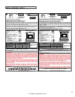
FOYER AU GAZ À ÉVACUATION - NE PAS UTILISER AVEC DU COMBUSTIBLE SOLIDE.

CONFORME AU STANDARD ANSI Z21.88-2014/CSA 2.33-2014 ET CAN/CGA-2.17-M91 (R2009).

CET APPAREIL DOIT ÊTRE INSTALLÉ CONFORMÉMENT AUX EXIGENCES DES CODES RÉGIONAUX ET DU CODE D’INSTALLATION ANSI 

NFPA 54-DERNIÈRE ÉDITION (ETATS-UNIS), OU CAN/CGA-B149.1-DERNIÈRE ÉDITION (CANADA). CET APPAREIL DOIT ÊTRE INSTALLÉ 

SELON LES DIRECTIVES D’INSTALLATION DU FABRICANT. POUR INSTALLATION DANS DES FOYERS À COMBUSTIBLE SOLIDE 

SEULEMENT - DE MAÇONNERIE OU PRÉFABRIQUÉ EN USINE. CE FOYER RADIANT AU GAZ À ÉVACUATION N’EST PAS CONÇU POUR ÊTRE 

UTILISÉ AVEC DES FILTRES À AIR.

CET APPAREIL DOIT ÊTRE UTILISÉ AVEC LE TYPE DE GAZ INDIQUÉ SUR LA PLAQUE SIGNALÉTIQUE ET PEUT ÊTRE INSTALLÉ DANS 

UNE MAISON PRÉUSINÉE OU DANS UNE MAISON MOBILE FIXE, LÀ OÙ LES CODES RÉGIONAUX LE PERMETTENT. VOIR LE MANUEL 

D’ENTRETIEN POUR PLUS DE DÉTAILS. CET APPAREIL NE PEUT PAS ÊTRE CONVERTI POUR L’USAGE AVEC D’AUTRES TYPES DE GAZ À 

MOINS D’UTILISER UNE TROUSSE DE CONVERSION HOMOLOGUÉE.

DANGER: RISQUE DE CHOC ÉLECTRIQUE. DÉBRANCHEZ L’APPAREIL AVANT D’EN FAIRE L’ENTRETIEN.

SI L’APPAREIL REQUIERT UN BRANCHEMENT ÉLETRIQUE, LES RACCORDEMENTS ET LA MISE À LA TERRE DOIVENT ÉTRE CONFORMES 

AUX EXIGENCES DES CODES RÉGIONAUX ET DU CODE D’INSTALLATION ANSI/NFPA 70 OU CSA C22.1.

DANGER:

 CET APPAREIL DÉGAGE DES TEMPÉRATURES ÉLEVÉES ET DEVRAIT ÊTRE INSTALLÉ À L’ÉCART DES 

ENDROITS TRÈS PASSANTS ET LOIN DES MEUBLES ET RIDEAUX. SURVEILLEZ LES ENFANTS QUI SE TROUVENT DANS LA PIÈCE. 

GARDEZ LA ZONE AUTOUR DU FOYER EXEMPTE DE MATÉRIAUX COMBUSTIBLES, D’ESSENCE ET AUTRES VAPEURS ET LIQUIDES 

INFLAMMABLES. MAINTENEZ LE BRÛLEUR ET LE BOÎTIER DES COMMANDES PROPRE EN TOUT TEMPS. VOIR LES MANUELS 

D’INSTALLATION ET D’ENTRETIEN QUI ACCOMPAGNENT L’APPAREIL. SEUL LE PANNEAU VITRÉ FOURNI PAR LE MANUFACTURIER 

PEUT ÊTRE UTILISÉ AVEC CET APPAREIL. EN AUCUN CAS, L’APPAREIL NE PEUT ÊTRE UTILISÉ SANS LA VITRE OU AVEC LA VITRE 

BRISÉE. LE REMPLACEMENT DE LA VITRE DOIT ÊTRE EFFECTUÉ PAR UN TECHNICIEN DE SERVICE QUALIFIÉ.

AVERTISSEMENT: UNE INSTALLATION INADÉQUATE DE MÊME QU’UN AJUSTEMENT, UNE MODIFICATION, UNE RÉPARATION OU UN 

ENTRETIEN INCORRECTS PEUVENT CAUSER DES BLESSURES OU DOMMAGES À LA PROPRIÉTÉ. RÉFÉREZ-VOUS AU MANUEL 

D’ENTRETIEN LIVRÉ AVEC CET APPAREIL. POUR DE L’ASSISTANCE, CONSULTEZ UN INSTALLATEUR QUALIFIÉ, UNE ENTREPRISE 

DE SERVICE OU UN FOURNISSEUR DE GAZ.

AVERTISSEMENT : RISQUE DE DOMMAGES OU DE BLESSURES SI L’APPAREIL N’EST PAS INSTALLÉ SELON LES INSTRUCTIONS 

DU FABRICANT OU SI DES PIÈCES AUTRES QUE CELLES SPÉCIFIQUEMENT APPROUVÉES AVEC CET APPAREIL SONT UTILISÉES.

N’ENLEVEZ PAS OU NE COUVREZ PAS CETTE ÉTIQUETTE

Part No. 900372-00  Rev. 0, 12/2014


MODÈLE

FABRIQUÉ PAR:

INNOVATIVE HEARTH PRODUCTS

1502 14TH ST NW

AUBURN, WA., USA 98001

Le numéro de série est indiqué dans la 

section anglophone de cette étiquette

SERIAL

 NO.

CET APPAREIL EST MUNI D’ÉQUIPEMENT POUR L’USAGE DU GAZ NATUREL. SI L’ÉTIQUETTE DU PANNEAU DES 

COMMANDES CONTREDIT CETTE ÉTIQUETTE, C’EST QUE LE TYPE DE CARBURANT DE CET APPAREIL A ÉTÉ CONVERTI.

La date de fabrication est indiquée dans la section anglophone de cette étiquette

Madison Park™ 27 CD

SPÉCIFICATIONS

Madison Park 27 CD (MPI27CD)

Utiliser uniquement avec l’écran 

no J4343. Suivre les instructions 

d’installation.

GAZ NATUREL

GAZ PROPANE

ENTRÉE MAX/MIN BTU/HR 0-4500 pi (0-1370 M)*

30 000 / 21 000

25 000 / 20 000

PRESSION À LA SORTIE  (IN. WC/C.E.)

3,5

10,0

PRESSION MINIMUM D’ENTRÉE DU GAZ (IN. WC/C.E.)

5,0

10,5

ORIFICE (DMS) 0-4500 pi (0-1370 M)*

#38

#53

*L’APPAREIL PRÉUSINÉ EST MUNI D’ÉQUIPEMENT POUR 0-2000 PIEDS (0-610 M). AU CANADA 0-4500 PIEDS (0-1370M).

SPÉCIFICATIONS ÉLECTRIQUE 120 VCA, 60 HZ, MOINS DE 2 AMPÈRES 

CHEMINÉE -  POUR LA SORTIE D’ÉVACUATION DES GAZ UTILISEZ UNE GAINE DE TUBAGE CERTIFIÉ SELON UL1777 OU ULC S635.  

CET APPAREIL DOIT ÊTRE RELIÉ À UN SYSTÈME D’ÉVACUATION TEL QUE SPÉCIFIÉ DANS LE MANUEL D’INSTALLATION DU 

FABRICANT.

EN ALTITUDE, AU-DELÀ DE 2000 PI/610 M, (AU CANADA 0-4500 PI/0-1370M) LA CAPACITÉ ÉNERGÉTIQUE DE L’APPAREIL DIMINUE DE 

QUATRE (4)% POUR CHAQUE 1000 PI (305 M).

DIMENSIONS MINIMUMS DE FOYER REQUISES

 .......

  MPI27CD

Ouverture avant ................................................................  27” (686mm)

Hauteur ..............................................................................  18" (457mm)

Largeur arrière  .................................................................  17" (432mm)

Profondeur  .......................................................................  15” (381mm)

DÉGAGEMENTS AUX COMBUSTIBLES

  A = 1-1/2" (38mm) Du bas de l’appareil au dessous de 

   la finition supérieure ..............................................  32" (813mm)

  B = Mur de côté ..............................................................  9-1/2" (241mm)

* C = 6” (152mm)


manteau de foyer à partir 

   de la base

................................................................  34" (864mm)

PROTECTION DU FOYER

  D = Distance verticale de la base de ....................................      0"                4”

   de l’appareil à l’extension d’âtre ....................................    (0mm)      (102mm)

  E = Extension d’âtre min. à l’avant .......................................    10"                 0"

   de l’appareil.........................................................................  (254mm)     (0mm)

*Voir le manuel d’entretien pour les informatinos supplémentaires reliées aux distances à respecter pour le manteau de foyer.

IGN ________

Note:  Extension d’âtre fabriqué avec 1/2” (13mm) 

minimum de matériaux non-combustible ou 

équivalent possédant un facteur k de 0.84.

Rapport nº 14-098

C

US

A

D

B

E

Mantel

DÉGAGEMENTS MINIMUMS

Manteau de foyer

C

Materiel non-combustible

Summary of Contents for Madison Park MPI27

Page 1: ...If you cannot reach your gas supplier call the fire department Installation and service must be performed by a quali fied installer service agency or the gas supplier WARNING FIRE OR EXPLOSION HAZARD Failure to follow safety warnings exactly could result in serious injury death or property damage AVERTISSEMENT RISQUED INDENDIE OU D EXPLOSION Le non respect Des avertissements de sécurité pour rait ...

Page 2: ...ALIENTE CAUSARÁ QUEMADURAS USTED DEBE NUNCA TOCAR EL VIDRIO CALIENTE LOS NIÑOS DEBEN NUNCA TOCAR EL VIDRIO L écran pare étincelles fourni avec ce foyer réduit le risque de brûlure en cas de contact accidentel avec la vitre chaude et doit être installé pour la protection Des enfants et Des personnes à risques incluse avec le façade Requis Unabarrera diseñadaparareducirelriesgodequemadurasdesdelamir...

Page 3: ... en funcionamiento Supervise en forma cercana a los niños en cualquier cuarto donde haya una chimenea funcionando para impedir el contacto con el vidrio Mantenga la ropa mobiliario gasolina y otros líquidos inflamables alejados de la chimenea Aún después de haber apagado el gas las superficies de la chimenea permanecen extremadamente calientes Asegúrese de colocar las Etiquetas de advertencia de s...

Page 4: ...List 12 Ratings 12 Insert and Fireplace Dimensions 13 Clearances to Combustibles 14 Insert Leveling 14 Installation 15 20 USING THIS MANUAL Please read and carefully follow all of the instructions found in this manual Please pay special attention to the safety instructions provided in this manual PRODUCT IS SUBJECT TO CHANGE WITHOUT NOTICE Venting Installation 15 Preparation For Flex Liner Install...

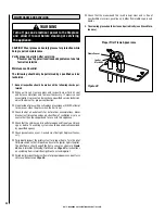
Page 5: ...ls viennent en contact avec la surface chaude Il est recommandé d installer une barrière physique si des personnes à risques habitent la maison Pour empêcher l accès à un foyer ou à un poêle installez une barrière de sécurité cette mesure empêchera les tout petits les jeunes enfants et toute autre personne à risque d avoir accès à la pièce et aux surfaces chaudes 7 Tout écran ou protecteur retiré ...

Page 6: ...ra quitarelpolvoyaceite Peguelaetiquetaadyacente alinterruptordecontroldelquemadorquecontrola elartefacto FiguraA Seleccioneelidiomaquemás se habla en la casa 2 Identifique el transmisor de control remoto y límpielo bien para quitar el polvo y aceite Pegue la etiqueta en la superficie del transmisor Figura B Seleccione el idioma que más se habla en la casa 3 Si no puede encontrar las etiquetas sír...

Page 7: ... étiquettesurleboîtier de la télécommande Figure B Choisissez la langue qui est principalement parlée dans la résidence du propriétaire En cas de doute collez l étiquette en anglais 3 Sivousneparvenezpasàlocaliserlesétiquettes s il vous plaît contactez IHP ou votre revendeur le plus proche pour recevoir IHP étiquettes d instructions de sécurité supplémentaires gratuitement Étiquettes de remplaceme...

Page 8: ...with heart or lung disease or anemia those under the influence of alcohol and those at high altitudes Turn off gas and electrical power to the appliance and allow it to cool before cleaning or servicing the appliance If the barrier becomes damaged the barrier shall be replaced with the manufacturer s barrier for this appliance Si l écran est endommagé il doit être remplacé par celui fournit par le...

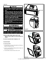
Page 9: ...er use solid fuels such as wood paper cardboard coal or any flammable liquids etc in this appliance Plated surfaces must be cleaned with glass cleaner and a clean soft cloth before firing the first time or fingerprints will remain permanently NEVER use brass polish to clean plated surfaces this will remove the plating CAUTION Hot while in operation Do not touch Severe Burns mayresult Keepchildren ...

Page 10: ...ed for use with either natural gas or propane Is NOT for use with solid fuels Is approved for sitting rooms and or bedrooms This appliance is suitable for installation into masonry or factory built fireplaces Fireplace Requirements These heaters are designed to be installed into an existing masonry fireplace built to UBC 37 or ULC S628 standards or factory built solid fuel wood burning fireplace l...

Page 11: ...be tested and certified by a nationally recognized testing and certification laboratory to ANSI American National Standard Institute gas appliance safety standards This appliance has been tested and certified to ANSI Z21 88 CSA 2 33 Standard for Vented Gas Fireplace Heater and CAN CGA 2 17 M91 and UL 307B Gas Burning Heating Appliances for Manufactured Mobile Homes in both USA and Canada This appl...

Page 12: ... details PRE INSTALLATION RATINGS MPI27 and MPI27CD NATURAL GAS LP GAS Max Min Input BTUh 0 2 000 Feet 0 610 M u 30 000 21 000 25 000 20 000 Manifold Pressure IN WC 3 5 10 0 Min Inlet Pressure IN WC 5 0 10 5 AFUE Efficiency MPI27 67 MPI27CD 67 MPI27 70 MPI27CD 69 P4 Efficiency v MPI27 68 MPI27CD 66 MPI27 71 MPI27CD 68 Orifice DMS 0 2 000 Feet 0 610 M u 38 53 uUnit factory equipped for 0 2000 FT 0 ...

Page 13: ...D Figure 3 Minimum Fireplace Cavity Figure 2 Insert Dimensions 26 5 8 676mm 16 3 4 425mm 8 3 4 222mm 10 7 8 276mm 14 7 8 378mm 17 7 8 454mm 14 3 8 365mm 20 3 4 527mm O D 2 15 16 75mm Minimum Fireplace Opening A 27 686mm Front Opening Width B 18 457mm Height C 17 432mm Rear Width D 15 381mm Fireplace Depth ...

Page 14: ...tandoffsorsurfacestocombustibleconstruction etc above the appliance Paint or lacquer used to finish the mantel must be heat resistant in order to avoid discoloration Facing and Mantel Clearances see Figure 4 The letters in Figure 4 A through E show minimum clearances required from the appliance to combustibles and the minimum projection of the hearth extension Figure 4 Clearances Insert Leveling A...

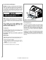
Page 15: ...ing and Termination Cap 46DVA CL33 Preparation For Flex Liner Installation The liner connector plate can be removed as shown in Figure 6 to make it easier to connect the flex liners to the intake and exhaust collars Re install the liner connector plate when the insert is placed in the fireplace NOTE Ensuregasketonconnectorplateisnotdamagedbeforere installing INSTALLATION Figure 6 Intake Liner Conn...

Page 16: ... not operate When done assure all connections are securely fastened NOTE Theminimumverticalrise exhaustvent is10feet 3 1M andthe maximum vertical rise is 25 feet 7 6 M These dimensions are measured from the base of the unit to the end of the vent pipe The fireplace and fireplace chimney must be clean and in good working order and constructed of non combustible materials Inspect chimney cleanouts f...

Page 17: ...amenée du gaz un orifice d au plus 38 1 mm 1 5 po peut être pratiqué selon les règles de l art dans la partie inférieure des parois ou au fond de la chambre de combustion Cet orifice doit être obturé au moyen d isolant incombustible une fois la conduite de gaz en place The installer must mechanically attach the marking supplied with the gas fireplace insert to the inside of the firebox of the fire...

Page 18: ...3 Figure 14 4 Place a layer of glowing embers rockwool directly over the ports Figure 11 A light layer will give a more constant rear flame A heavy layer will give more glow but may need to be adjusted after light up to prevent sooting and poor flame quality 5 Place volcanic stones around the perimeter of the glowing embers rockwool in the areas shown in Figure 12 IMPORTANT Do not cover ports with...

Page 19: ... supplied with this manual Figure 16 Surround Mounting Tab Surround Mounting Tab Facade Mounting Tab Figure 15 Firebox Media Installation Optional kit See Page 35 for ordering information 1 Measure out approximately 3 cups of glass media and place an even layer on burner as shown in Figure 15 Care should be taken to NOT block pilot opening in burner tray or mound up media 2 Remove reflective accen...

Page 20: ...ting insert a small flat blade screwdriver into the tap and turn a half turn counter clockwise Cover the tap with the line from the manometer and check the pressure Again close the tap gently but securely after completing the check Check the taps for gas leaks with a gas leak test solution retighten if necessary If the pressure is not sufficient make sure the gas supply line is large enough the su...

Page 21: ...ust the air shutter slide the adjustment lever side to side see Figure 18 CAUTION The air shutter should never be set so as to make the tips of the flames sooty or create sooting on the viewing glass logs or heat exchanger If soot begins to form after burning the air shutter should be opened gradually until the sooting condition stops Gas quality and gas pressure may vary which can affect the burn...

Page 22: ...tric power to the appliance if service is to be performed 3 Close the main line gas shut off valve WARNING If you do not follow these instructions exactly a fire or explosion may result causing property damage personal injury or loss of life A This appliance is equipped with an ignition device which automatically lights the pilot Do not try to light the pilot by hand B BEFORE OPERATING smell all a...

Page 23: ...standing pilot simply by using the remote to switch from IPI to CPI This is done when the remote is in the off position Press the mode key and use the up down arrow key to change between IPI and CPI To save energy switch to intermittent mode To have a standing pilot which will help startup during cold climate conditions by warming the flue and the glass switch to standing pilot The standing pilot ...

Page 24: ...ystem or activating manual bypass of the remote system CAUTION Propertydamagehazard Excessiveheatcancause propertydamage Theappliancecanstaylitformany hours Turn off the appliance if it is not going to be attended for any length of time Always place the Transmitter where children can not reach it Figure 22 Remote transmitter Figure 21 ON OFF Key THERMOSTAT Key UP DOWN Arrow Key MODE Key Blue LCD D...

Page 25: ...s turned off The Up Arrow Key will increase the flame height each time it is pressed If the Up Arrow Key is pressed while the system is on but the flame is off the flame will come on in the high position see Figure 25 A single beep will confirm reception of the command Room Thermostat Remote Operation The Remote Control can operate as a room thermostat The thermostat can be set to a desired temper...

Page 26: ... heat up and the flames will become a yellow orange color Adjusting the appliance to cause the flames to turn orange sooner may result in poor combustion sooting and a hazardous situation See Figure 26 showing proper flame appearance When testing for proper operation If an optional thermostat is installed adjust it to its highest temperature setting Visually determine that main burner gas is burni...

Page 27: ... commandes étiquetez tous les fils avant de les débrancher Des erreurs de cáblage peuvent entraîner un fonctionnement inadéquat et dangereux VALVE BURNER PILOT ON OFF SWITCH PILOT ROOM AIR BLOWER BATTERY HOLDER ACCENT LIGHT POWER CORD GRN YLW BLK BRN YLW ORG ORG RED BLK WHT BLK WHT GRN GRN YLW ORG WHT GRN WHT BLU BLU BLK 1 4 PRG BUTTON X6 X5 X4 X3 X2 X1 X10 X11 FEMALE DISCONNECT MALE DISCONNECT ST...

Page 28: ...an those approved for use with this appliance o Check that the chimney and its outlet are open and free of soot block age or debris The venting system should be periodically examined by a qualified agency o Check gaskets once a year Gaskets must be tight Replace if neces sary o Periodically inspect the pilot system for proper flame Turn the pilot ON Auto switch to the ON position Ensure the ignite...

Page 29: ...on these doors or replace cracked or broken glass Handle this glass with extreme care Glass is susceptibletodamage Donotscratchorhandle roughly while reinstalling the glass door frame The glass door s of this appliance must only be replaced as a complete unit as provided by the manufacturer Donotattempttoreplacebroken cracked or chipped glass separately Do not attempt to touch the front enclosure ...

Page 30: ...lectrical Code Part 1 CSA C22 1 latest edition See Operating Options for burner ON OFF switch information Figure 31 Blower Assembly Removal Blower Assembly Fireplace Insert Back Repair If the glass is broken in the glass door the entire door metal frame gasket and glass should be replaced as a unit This replacement glass door is available from your IHP dealer Do not use substitute parts or materia...

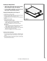
Page 31: ...emporary and Santa Fe Facades a Using a 3 8 nut driver remove and set aside the four nuts and Z brackets holding each corner of the barrier in place b Remove the damaged barrier from the facade and discard Deco Facades a Using a 3 8 nut driver remove and set aside the two nuts and Z brackets holding the top corners of the barrier in place b Using a flat blade screwdriver careful pry up the two tab...

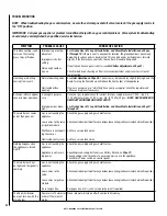
Page 32: ...on on Page 17 through 20 The main Burner comes on but then goes out Gas is not reaching the appliance Loose wires to the valve or ignition module Pilot flame is not engulf ing the sensor Obstructed vent system Check the gas supply and gas shutoff valves Checkcontrolcompartmentforanyobviousloosewiring callaservicetechnicianifrequired Call for a service technician Call for a service technician Nothi...

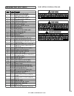
Page 33: ...rd Thermal Barrier Kit 14 H9178 Façade Mounting Bracket Kit set of two 15 H9183 Refractory Panel Retaining Bracket Kit two sets one of each style 16 H9181 Media Burner Support Tray Kit MPI27CD only 17 H9170 Media Burner Assembly includes shutter assy MPI27CD only 18 H9182 Media Burner Accent Glass MPI27CD only 19 H9180 Log Support Panel Kit MPI27 only 20 H9169 Log Burner Assembly MPI27 only 21 H91...

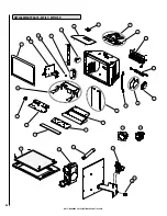
Page 34: ...34 NOTE DIAGRAMS ILLUSTRATIONS ARE NOT TO SCALE REPLACEMENT PARTS MPI27 MPI27CD 1 2b 4 5 6 7 8 9 10 11 12 13 14 15 16 3a 3b 17 20 19 21 22 23 2a 18 24 25a 25b 26 3A 3B 3b 3a ...

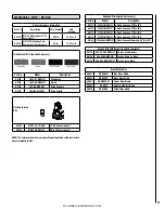
Page 35: ... MPI27 Madison Park 27 Small Insert 87 5 lb 12 22 cu ft H9123 MPI27CD Madison Park Contemp 27 Small Insert 80 lb 12 22 cu ft Surround Kits required accessory Cat No Model Description H9131 FP2637 MPDVI27 3 Sided Surround 37 W x 26 H H9132 FP2641 MPDVI27 3 Sided Surround 41 W x 26 H H9133 FP3037 MPDVI27 3 Sided Surround 37 W x 30 H H9134 FP3041 MPDVI27 3 Sided Surround 41 W x 30 H H9135 FP3846 4S M...

Page 36: ...38mm Du bas de l appareil au dessous de la finition supérieure 32 813mm B Mur de côté 9 1 2 241mm C 6 152mm manteau de foyer à partir de la base 34 864mm PROTECTION DU FOYER D Distanceverticaledelabasede 0 4 del appareilàl extensiond âtre 0mm 102mm E Extensiond âtremin àl avant 10 0 del appareil 254mm 0mm Voir le manuel d entretien pour les informatinos supplémentaires reliées aux distances à resp...

Page 37: ...SI NFPA 54 DERNIÈRE ÉDITION ETATS UNIS OU CAN CGA B149 1 DERNIÈRE ÉDITION CANADA CET APPAREIL DOIT ÊTRE INSTALLÉ SELON LES DIRECTIVES D INSTALLATION DU FABRICANT POUR INSTALLATION DANS DES FOYERS À COMBUSTIBLE SOLIDE SEULEMENT DE MAÇONNERIE OU PRÉFABRIQUÉ EN USINE CE FOYER RADIANT AU GAZ À ÉVACUATION N EST PAS CONÇU POUR ÊTRE UTILISÉ AVEC DES FILTRES À AIR CET APPAREIL DOIT ÊTRE UTILISÉ AVEC LE TY...

Page 38: ...entraînant des dommages des blessures ou la mort A Cet appareil est muni d un dispositif d allumage qui allume automatiquement la veilleuse Ne tentez pas d allumer la veilleuse manuellement B AVANT DE FAIRE FONCTIONNER reniflez tout autour de l appareil pour déceler une odeur de gaz Reniflez près du plancher car certains gaz sont plus lourds que l air et peuvent s accumuler au niveau du sol QUE FA...

Page 39: ...mage to the Product will produce excessive temperatures and could result in a fire hazard c damages caused by failing to provide proper maintenance and service in accordance with the instructions provided with the Product d damages repairs or inefficiency resulting from faulty installation or application of the Product IHP is not responsible for inadequate fireplace system draft caused by air cond...

Page 40: ... your IHP distributor or dealer Parts will be shipped at prevailing prices at time of order When ordering repair parts always give the following information 1 The model number of the appliance 2 The serial number of the appliance 3 The part number 4 The description of the part 5 The quantity required 6 The installation date of the appliance If you encounter any problems or have any questions conce...

Reviews: