15
NOTE: DIAGRAMS & ILLUSTRATIONS ARE NOT TO SCALE.
Venting Installation
Your IHP appliance must be vented to the outside in accordance with the
current edition of the National Fuel Gas Code ANSI-Z223.1 (In Canada,
the current CAN/CGA B149.1 installation code).
This appliance requires a 3” diameter listed flex liner. The vent should
terminate with a listed direct-vent termination cap. The chimney should be
sealed around the cap to prevent air and rain from entering the chimney.
Adhere to the vent manufacturer's instructions for installation and vent
termination. These appliances are approved for use with the following
vent kits.
Simpson Dura Vent -
Flex Liner 3" X 35' - #3DFA-35
Adaptor w/ Flashing - #46DVA-GK
Termination Cap - #46DVA-VCH With #460 DVA-VWG
Termination Cap - #460DVA-VC
Co-Linear Kit w/ 3" X 35' Flex Liner (Intake and Exhaust), Adaptor, Flashing
and Termination Cap - #46DVA-CL33
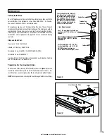
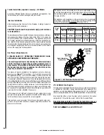
Preparation For Flex Liner Installation
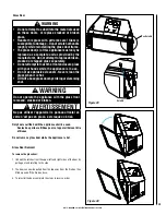
The liner connector plate can be removed (as shown in
Figure 6)
to make
it easier to connect the flex liners to the intake and exhaust collars. Re-
install the liner connector plate when the insert is placed in the fireplace.
NOTE: Ensure gasket on connector plate is not damaged before re-installing.
INSTALLATION
Figure 6
Intake
Liner Connector Plate
Exhaust
Vertical Cap
Termination
Connector
Exhaust
Intake
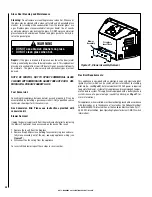
The existing fireplace chimneys
may take various contours which
the flexible liners will accommo-
date. However, keep the flexible
liner VERTICAL and avoid bend-
ing. When at maximum vertical
height, standing pilot should be
used for correct operation.
Liner Requirements:
Vertical Height Min. = 10 ft. (3.1 M)
Vertical height Max. = 25 ft. (7.6 M)
NOTE: Measured from base on
unit to the end of the vent pipe or liner
Use 3" (76 mm) diameter listed gas
vent liner (UL1777 ONLY) for the
EXHAUST
Use 3" (76 mm) diameter listed
liner (UL 181 or UL1777) for the
AIR INTAKE.
Figure 5


