4-30 Edit Menu
889691
eZ-Analyst
Edit Menu > Configuration >
FFT Setup Tab:
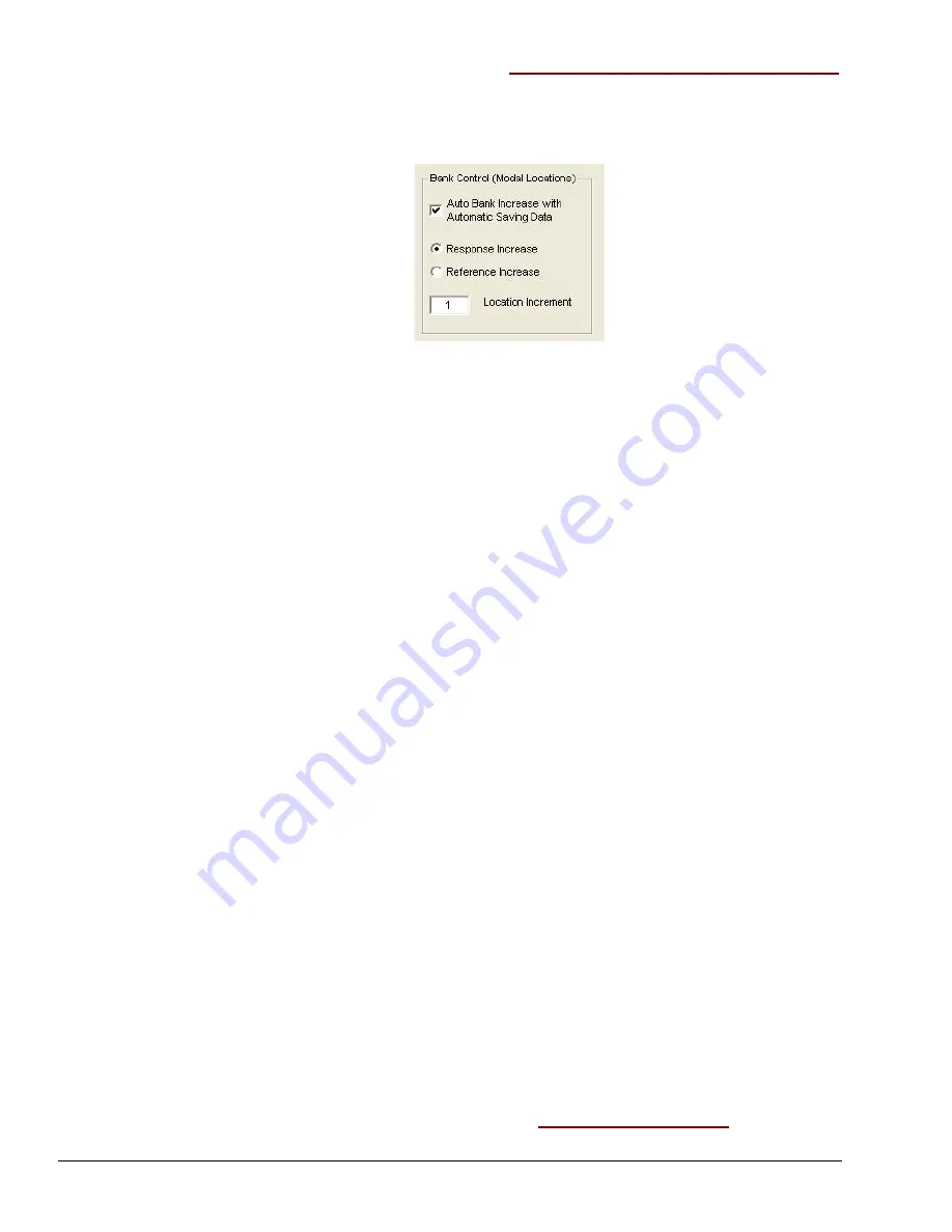
Bank Control (Modal Locations) Panel
This panel relates to the Modal Locations window, which is accessed from
eZ-Analyst
Window’s pull-down menu. The Bank Control (Modal Locations) Control Panel contains one
check box, two radio buttons, and a location increment field. Descriptions of each follow.
Bank Control (Modal Locations)Panel
Note
: This option is only effective when the
averaging mode
is used.
Auto Bank Increase
with Automatic
Saving Data
:
A Bank is a set of response channels. You can have
eZ-Analyst
increment the banks automatically after each measurement, or
you can manually increment the banks. The number of active
channels is used as the skip factor for bank switching.
If the Auto Bank Increase checkbox is checked, then the bank is
automatically incremented, but only when the automatic saving
data option is selected at Setup Export Function Data menu.
Response Increase
:
If the
Response Increase
radio-button is selected, the reference
channel’s location doesn’t change. The response’s location(s) are
increased [or decreased] for next available location numbers.
Reference Increase
:
If the
Reference Increase
radio-button is selected, the response
channel’s location doesn’t change. The reference’s location(s) are
increased [or decreased] for next available location numbers.
Location Increment
:
Indicates the number by which eZ-Analyst is to increment the
response or reference location after each measurement.
Note
: Decreasing location numbers are only available with the manual bank <Down>
button on the Modal Locations window. Modal Locations is accessed from the
Windows pull-down menu.
A Note About Channel Pairs
A Channel Pair is a
Reference
channel and a
Response
channel that are used to display a dual-
channel function, such as an FRF (Frequency Response Function). Channel Pairs are
automatically defined when a user selects "Reference" channel type for an input channel. For
example, if Channels 1 and 2 were defined as reference channels, then all response channels
would paired to those channels. Thus,
1,1
2,1
3,1
4,1
5,1
6,1
7,1
8,1 and
1,2
2,2
3,2
4,2
5,2
6,2
7,2
8,2
To export all of the data for the Channel Pairs, select the “All Ch. Pairs” radio button in the
Export Function Data window (see chapter 3 for window details).
Edit Menu > Configuration >
FFT Setup Tab:
Low Frequency Cutoff


