


Operation Manual of INVT CHS100 AC Servo Drive 6 Detailed parameter description
89
Function
code
Name
Unit
Range
Default
Mode
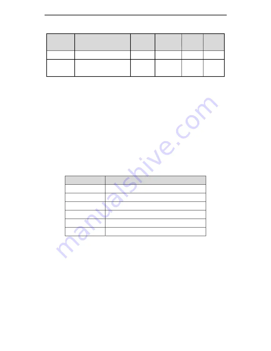
Pc.42
Voltage upper limit of AO 2
V
0.00~10.00
10.00
P.S.T
Pc.43
Corresponding of upper
limit of AO 2
% 0.0~100.0
100.0
P.S.T
This group of parameters defines the relationships between the analog output voltage
and its corresponding setting. When the analog output voltage exceeds the set upper
limit or lower limit range, the part beyond will be calculated with the upper limit or lower
limit.
AO1 indicates the signal outputted from the analog output 1 (AO1) terminal. AO2
indicates the signal outputted from the analog output 2 (AO2) terminal. The output
signal has no directionality. All output values represent the absolute values of the
setting signals.
The specific meanings of AO signals are selected by Pc.48 and Pc.49. The
corresponding settings of the upper/lower limits are expressed by a percentage. The
maximum is taken as 100% and the determination of the maximum is listed in the table
below:
Outputs
Maximum
Motor speed
5000r/min
Output torque
3 times of the servo motor rated torque
Output current
3 times of the servo motor rated current
Bus voltage
500V
Speed setting
5000r/min
Torque setting
3 times of the servo motor rated torque
Take a 1.5kW servo drive as an example. We want to output the actual speed from the
analog output 1 terminal (AO1) to observe and require that 8V corresponds to
5000r/min and 0V corresponds to 0r/min. On this condition, set Pc.44=0, Pc.36=0.00,
Pc.38=8.00, Pc.37=0.0, Pc.39=100.0, the relationship between the actual speed
setting and the output voltage is shown in the figure as below:


