


Operation Manual of INVT CHS100 AC Servo Drive 4 Signal and wiring
37
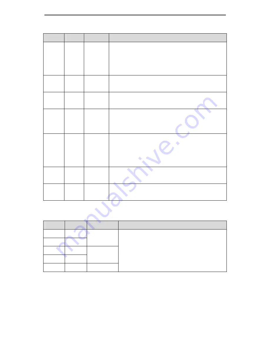
Symbol Pin No.
Name
Function
ALM
15 Servo alarm
When the servo drive is in normal state, this signal
output transistor is breakover. When the power supply
is disconnected or the servo drive is in alarm state,
this signal output transistor switches off.
LM 13
Torque
limit
When the servo system is in torque limit, this signal
output transistor is breakover.
PLR 11
Position
reaching
When the position reaches to the command range,
this signal output transistor is breakover.
BRK 9
Brake
releasing
When it comes into the brake releasing sequence and
needs to release the brake, this signal output
transistor is breakover.
RDY 14
Servo ready
When the control power and main power are applied
normally and the drive is not in alarm state, this signal
output transistor is breakover, it means the drive can
be started.
SR 30
Speed
reaching
When the speed reaches the range of speed setting,
this signal output transistor is breakover.
ZSO 29
Zero
speed
When the speed reaches the range of zero speed, this
signal output transistor is breakover.
4.5.8.7 Encoder output signals and their functions
Table 4-9 Function table of encoder output signals
Symbol Pin No.
Name
Function
OA+ 44
OA- 43
Phase A
output
OB+ 41
OB- 42
Phase B
output
OZ+ 28 Phase
Z
y
Output the frequency divided encoder signal,
comply with the standard of TIA/EIA-422-B;
y
The output phase A pulse and phase B pulse is
still orthogonal. When it rotates forward, phase
B leads phase A by 90º. When it rotates in


