


Operation Manual of INVT CHS100 AC Servo Drive 7 Gain adjustment
105
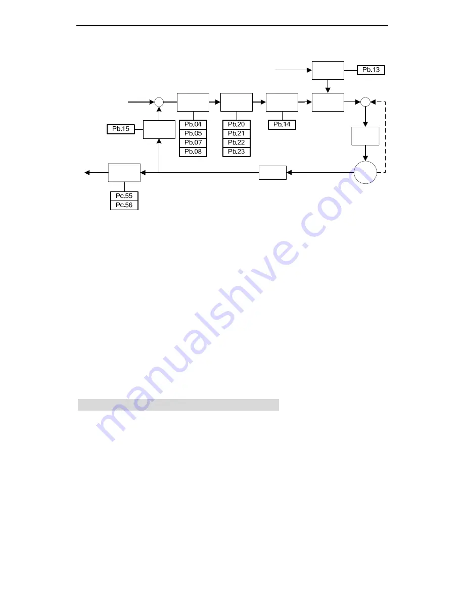
Fig. 7-3 Block diagram of torque control
The general procedures for parameter adjustment in the torque mode are:
1) Initial setting of the parameters
The defaults of the parameters can be recovered by the default parameter recovering
operation (see chapter 5.2.4 for details).
2) Adjustment of the torque smoothing filter
In the case the analog torque command is inputted, we can adjust the torque
smoothing filter time constant (Pb.13) to make the torque change smoothly.
3) Frequency division of the feedback pulse output
If the feedback pulse of the encoder needs to be outputted, the frequency division
coefficient of pulse output (Pc.55, Pc.56) can be used to change the frequency of the
output pulse.
7.2 Suppression of mechanical resonance
The mechanical system has a certain resonant frequency. If the response speed of the
servo is improved, the system may resonate (oscillation and abnormal noise) near the
mechanical resonant frequency. The resonance of the mechanical system can be
effectively suppressed by setting the parameters of the trap wave filters.
The trap wave filters achieve the goal of suppressing mechanical resonance by
decreasing the gain of certain frequency. We can set the frequency to be suppressed
as well as the suppression extent with relevant parameters.
This servo drive has two trap wave filters which can be set with Pb.20, Pb.21 and
Encoder
frequency
division
Torque
controlle
r
Encoder
Motor
Torque command
Torque
command
processing
Speed
controller
Trap filter
Low-pass
filter
Torque limit
Speed limit command
Speed test
filter


