Invacare 3LX Service Manual Download Page 31

31

P

R

E
V

M

A

I

N

T

E

N
A
N
C

E

5

L
T

R

C

O
M

P

R
E
B
U

I

L

D

PROCEDURE 2 - PREVENTIVE MAINTENANCE (continued)

PREVENTIVE MAINTENANCE

PROCEDURE 2

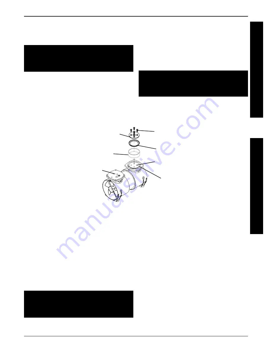
Installing the New Teflon Rings and Piston
Heads (FIGURE 12)

4. Install and tighten the phillips head screws until

snug to align the Teflon ring with the aluminum
sleeve.

5. Once the Teflon ring is centered properly with the

piston head and aluminum sleeve, torque the
screws to 30 in. lbs.

CAUTION

Piston head MUST be rotated 90

O

 when rein-

stalling. This ensures proper wear on the pis-
ton head and will prolong it's life.

1. Place the aluminum sleeve onto its mounting

position on the compressor housing.

2. Rest the new Teflon ring on the aluminum sleeve

and center the ring with the piston head.

3. Install the piston head over the piston ring and

into the aluminum sleeve.

One (1) Piston

Rebuild ONLY

SHOWN for Clarity

Phillips Head

Screws

(4 per Head)

Piston

  Teflon Ring

Aluminum Sleeve

Piston Head

Valve Plate

FIGURE 12 - INSTALLING THE NEW TEFLON RINGS AND PISTON HEADS

Mounting Position for

Aluminum Sleeve

CAUTION

DO NOT force aluminum sleeve onto piston. The
Teflon ring may become damaged and
render the piston unusable.

Installing Top and Bottom Flappers (FIGURE
13)

NOTE: Ensure that new valves are facing in the
same direction that the old ones when install-
ing and that they completely cover the compres-
sion opening in the valve plate. Make sure that
no dirt or grease contacts the valves or valve
plates as this may inhibit their ability to open
and close properly and severely reduce the
compressor's ability to adequately compress the
air.
 Replace the top and bottom valves by doing
one side of the valve plate at a time.

CAUTION

Because of tooling of the valve keepers, ensure
that the word "UP" on the valve keeper is fac-
ing you when installing the valve keepers.

1. Use the small common (flathead) screwdriver

to remove the valve screw securing the valve
restraint, valve keeper, and valve to the top of
the valve plate.

2. Remove the valve screw, valve keeper, and valve

from the bottom side of the valve plate.

3. Reverse STEPS 1-2 to install the NEW top and

bottom valves onto the valve plate.

4. Torque valve screws to 12 in. lbs.

5. Install the head gasket in the compressor head

and the valve plate gasket into the underside of
the valve plate.

6. After the other piston has been rebuilt, install the

valve plates over the aluminum sleeves and rein-
stall the head assembly onto the valve plates not-
ing the markings made when the head assembly
and valve plates were removed.

Summary of Contents for 3LX

Page 1: ...del 5LXO2T with SensO2 Model 6LXO2 with SensO2 Model 6LXO2T with SensO2 Model 6LXO2H with SensO2 Model 6LXO2HT with SensO2 INVACARE 3 5 Model 3LX Model 5LX SERVICE MANUAL DEALER KEEP THIS MANUAL THE PROCEDURES IN THIS MANUAL MUST BE PERFORMED BY AN AUTHORIZED DEALER ONLY ...

Page 2: ... NOTICE THE INFORMATION CONTAINED IN THIS DOCUMENT IS SUBJECT TO CHANGE WITH OUT NOTICE WARNING DO NOT OPERATE THIS EQUIPMENT WITHOUT FIRST READING AND UNDERSTANDING THIS MANUAL IF YOU ARE UNABLE TO UNDERSTAND THE WARNINGS AND INSTRUCTIONS CONTACT A HEALTHCARE PROFESSIONAL DOCTOR THERAPIST BEFORE ATTEMPTING TO USE THIS EQUIPMENT OTHERWISE INJURY OR DAMAGE MAY RESULT SAVE THESE INSTRUCTIONS ...

Page 3: ... REPLACING P E VALVE 5LX 6LX 5LXO2 6LXO2 38 PROCEDURE 4 REPLACING SIEVE BEDS 39 PROCEDURE5 REPLACINGCHECKVALVES 40 PROCEDURE 6 REPLACING ADJUSTING REGULATOR 41 Replacing Regulator 41 AdjustingRegulator 42 PROCEDURE 7 REPLACING COMPRESSOR ASSEMBLYORCAPACITOR 43 ReplacingCompressorAssembly 43 Replacing Capacitor 43 PROCEDURE 8 REPLACING HEAT EXCHANGER 44 PROCEDURE 9 REMOVING CONTROL PANEL 45 PROCEDU...

Page 4: ...ped or damaged or dropped into water call Qualified Service Personnel for examination and repair Keep the cord away from HEATED or HOT surfaces NEVER drop or insert any object into any opening NEVER block the air openings of the product or place it on a soft surface such as a bed or couch where the air opening may be blocked Keep the openings free from lint hair and the like Fill humidifier with w...

Page 5: ...HE RISK OF BURNS ELECTROCUTION FIRE OR INJURY TO PERSONS WARNING This device is to be used only in accordance with the prescription of a physician and this Owners Manual If at any time the patient or attendant conclude that the patient is receiving an insufficient amount of oxygen the supplier and or physician should be contacted immediately No adjust ments should be made to the flowrate unless pr...

Page 6: ...alified electrician or serviceman if the grounding instructions are not completely understood or if doubt exists as to whether the product is properly grounded B This product is for use on a normal 120 V circuit and has a grounding plug that looks like the plug illustrated in sketch A shown at the bottom of the page A temporary adapter which looks like the adaptor illustrated in sketches B and C m...

Page 7: ...rcuit Breaker Oxygen Outlet Flowmeter Oxygen Outlet Power Indicator Light Power Switch Cabinet Filter 2 ea FEATURES 3LX 5LX Circuit Breaker Flowmeter Power Indicator Light Elapsed Time Meter SensO2 Status Indicator Lights 5LXO2 5LXO2T 6LXO2 and 6LXO2T ONLY FEATURES 5LXO2 5LXO2T 6LXO2 6LXO2T ...

Page 8: ...Pa 3 45 kPa 34 5 kPa 3 45 kPa SensO2 Alarm Thresholds Factory Preset at 73 Indicators O2 Purity Over 85 2 73 3 to 85 2 Below 73 3 Internal Switch Set at 73 GREEN Indicator Light YELLOW Indicator Light RED Indicator Light Continuous Audible Alarm Sieve GARDTM Compressor Shutdown Internal Switch Set at 85 GREEN Indicator Light RED Indicator Light Continuous Audible Alarm Sieve GARDTM Compressor Shut...

Page 9: ...ches 35 6 cm Weight 54 lbs 24 5 kg All 5LX and 6LX Models 53 lbs 23 9 kg 3LX Shipping Weight 59 lbs 27 kg All 5LX and 6LX Models 58 lbs 26 1 kg 3LX Operating Temperature Exhaust Less than Ambient 35O F 16O C Oxygen Output Less than Ambient 4O F 2O C Cabinet Impact Resistant flame retardant plastic cabinet Regulatory Listing ETL certified complying with applicable portions of UL 1431 Temperature 50...

Page 10: ... Invacare The air compressor suspension system has been engineered to withstand severe motion and orientation UNPACKING FIGURE 1 1 Check for any obvious damage to the carton or its contents If damage is evident notify the carrier or Invacare 2 Remove all loose packing from the carton 3 Carefully remove all the components from the carton NOTE After inspection unless the Invacare Oxygen Concentrator...

Page 11: ...creased pressure creates increased temperature a heat exchanger is utilized to lower the tempera ture by 20O F 6 7O C before the air enters the 4 way valve It is then channeled to a sieve bed containing the adsorption material A restrictor downstream of the sieve bed causes pressure to build up inside the sieve bed which is necessary for the adsorption process A small amount of relatively pure oxy...

Page 12: ...are that interprets the signal being received from the sensor It compares the signal to clinically acceptable limits that have been selected with the indicator switch mounted on the PC board Signals outside of the clinically acceptable limits generate responses in the form of lighted LEDs audible indicators and or system shut down Operating Sequence Once the power switch has been turned ON the Sen...

Page 13: ...PRESSURE REGULATOR SOLENOID PILOT VALVE 4 WAY VALVE CHECK VALVES and ELECTRICAL CONNECTIONS LEGEND CABINET GROSS PARTICLE FILTER RESONATOR TEST POINT 1 OXYGEN CONCENTRATOR OUTLET FLOW RESTRICTOR P C BOARD P1 TEST POINT 2 BETWEEN PRODUCT TANK AND CHECK VALVE OPTIONAL OXYGEN SENSOR RESTRICTOR ASSEMBLY IRC3LX IRC5LX ONLY FLOWMETER RESTRICTOR is EXTERNAL on IRC3LX ONLY It is INTERNAL to P E VALVE for ...

Page 14: ...l outlet with a tablelamp or voltmeter set on 150 200 VAC scale If outlet isn t working check protective device in home s electrical panel or consult an electrician Also ensure that unit is properly plugged in DO NOT use extension cords Move to another outlet or circuit 2a Replace cord 2b Replace power cord connectors on plug 2c Reattach connector 3a Check all electrical connections to the On Off ...

Page 15: ...rd PROCEDURE 11 b Disconnected Wire 2 4 way Valve a Not Shifting NOTE REFER TO THE REPAIR REPLACEMENT GUIDE IN THIS MANUAL FOR PROPER REPLACEMENT OR ADJUSTMENT PROCEDURES 4 Reset breaker NOTE Breaker may trip to safe guard concentrator during a power surge If breaker trips immediately there is a probable short in the unit Check for pinched or charred wires If the breaker does not trip run unit for...

Page 16: ...place or retighten 3b Replace or retighten tubing Re place Heat Exchanger PROCE DURE 8 LOW PRESSURE Internal Status Indicators RED On GREEN On LX Control Board RED One 1 Flash GREEN One 1 Flash Integrated Sensor Board LX SMT Board Unit plugged in power switch on continuous audible alarm Com pressor shut down Failure to cycle due to low pressure 4 Replace PROCEDURE 6 4 Regulator cracked or leaking ...

Page 17: ... Dirty 3 Compressor a Defective b Faulty Capacitor c Bad Motor Windings d Worn Seals e Bad Bearings f Leak at fittings or tubing 3a Replace Compressor PROCE DURE 7 3b Replace Capacitor PROCE DURE 7 3c Replace Compressor PROCE DURE 7 3d Rebuild Top End of Compres sor PROCEDURE 2 3e Replace Compressor PROCE DURE 7 3f Replace Fittings or Tubing 2 Inlet Filter Dirty 4 Heat Exchanger a Leak at tubing o...

Page 18: ...sonator a Damaged or missing b Tubing disconnected or dam aged 3 Inlet Filter missing 4 Compressor 12 To accommodate for varying tolerances when replacing com ponents an adjustable timer is used to control the shifting of the Invacare 5 Pressure Equaliza tion P E Valve PROCE DURE 18 13a Replace P E Valve PROCE DURE 3 13b Replace P E Valve PROCE DURE 3 1a Check pressure at oxygen outlet Adjust Regu...

Page 19: ...e down 4 Heat Exchanger a Fins dirty or plugged b Fins damaged 5 Compressor a Defective b Faulty capacitor c Bad motor windings d Worn seals e Bad bearings 6 Line Voltage excessive surge 6 Have line voltage inspected by certified electrician A voltage regulator may be required and is obtainable from your local elec tric company 5a Replace compressor PROCE DURE 7 5b Replace capacitor PROCE DURE 7 5...

Page 20: ...nector to harness 2 Horn Disconnected 1 Purity Switch Defective SYMPTOM PROBABLE CAUSE SOLUTION 1 Transformer Assembly a Molex connector disconnected from P C Board b Faulty transformer assembly UNIT NOT OPERATING Internal Status Indicators RED Three 3 Flashes GREEN One 1 Flash Integrated Circuit Board Control Panel Indicators RED Off YELLOW Flashing GREEN On UNIT NOT OPERATING Internal Status Ind...

Page 21: ...ONCENTRATOR FROM ELECTRICAL OUTLET BEFORE SERVICING 1 Unplug unit 2 Remove the eight 8 mounting screws that secure cabinet assembly to the base assembly 3 Lift the cabinet straight up NOTE When required vacuum inside of the cabinet and exposed foam insulation 4 To re install cabinet reverse STEPS 2 3 Cabinet Assembly Mounting Screws 8 each FIGURE 1 REMOVING CABINET CABINET PROCEDURE 1 Base Assembl...

Page 22: ...ding upon the environment the concen trator is used in 1 Unplug unit 2 Remove cabinet Refer to PROCEDURE 1 REMOVING CABINET 3 Unscrew the inlet filter located on the top left of the sound box counterclockwise 4 Discard existing inlet filter and replace with a NEW inlet filter 5 Reinstall cabinet Refer to PROCEDURE 1 REMOVING CABINET FIGURE 3 BACTERIA FILTER Bacteria Filter FIGURE 3 1 Unplug unit 2...

Page 23: ... and muffler if plugged or restricted b Install NEW exhaust muffler if canister is in good condition 8 Install NEW re install existing muffler canister by reversing STEPS 3 5 9 Reinstall cabinet Refer to PROCEDURE 1 REMOVING CABINET FIGURE 4 EXHAUST MUFFLER CANISTER EXHAUST MUFFLER Ty wraps Rear of Sound Box Mounting Screw s Exhaust Tubing From 4 way Valve Manifold Exhaust Muffler Canister Exhaust...

Page 24: ...or Heads and Replacing Crossover Tube O Rings FIGURE 6 1 Unplug concentrator 2 Carefully remove compressor from concentrator Refer to PROCEDURE 7 REPLACING COMPRESSOR ASSEMBLY OR CAPACITOR 3 Use the Phillips screwdriver to remove the twelve 12 screws that secure the head assembly and valve plates to the compressor 4 Mark the heads and valve plates to ensure proper reinstallation and set valve plat...

Page 25: ...h Allen wrench to remove the set screw located at the base of the connecting rod NOTE It may be necessary to pry the spread point of the connecting rod to loosen it from the bear ing of the eccentric 6 Carefully slide the eccentric out of the compres sor housing and set aside 7 Remove the aluminum sleeve from the piston 8 Tilt the piston slightly and with the other hand slide the lower portion of ...

Page 26: ...aring leaving a clearance of 032 1 16 inch 6 Apply a small amount of Hernon 423 to threads of connecting rod screw 7 Install connecting rod screw and torque to 15 in lbs DO NOT OVERTIGHTEN CAUTION DO NOT force aluminum sleeve onto piston The Teflon ring may become damaged and make the piston unusable 8 Turn the eccentric until piston is in the full up position 9 Place the aluminum sleeve partially...

Page 27: ... completelycoverthecompressionopeninginthevalve plate Ensure that no dirt or grease contacts them as this may inhibit their ability to open and close properly and severely reduce the compressor s ability to ad equately compress air CAUTION Because of tooling of the valve keepers ensure that the word UP on the valve keeper is facing you when installing the valve keepers 1 Replace the top and bottom...

Page 28: ...ITINSTALLATIONANDBEDPRESSURECHECKintheIRC3LX IRC5LX IRC5LXO2SER VICEMANUAL Compression Opening under Flapper Valve Plate Head Valve Plate Gasket Valve Screw Valve Plate Gasket BOTTOM SIDE Valve Plate Mounting Phillips Head Screws 6 per Head Compression Opening under Valve Valve Keeper Valve Screw Valve TOP SIDE Valve Keeper Valve Head Gasket Head FIGURE 9 INSTALLING THE TOP AND BOTTOM FLAPPERS AND...

Page 29: ...r 4 Valve Screws 9 Four 4 Connector Crossover Tube O Rings Tools Required One 1 Phillips Head TORX T 25 Driver One 1 Phillips 2 Screwdriver Attachment for Torque Wrench for Retainer Screws One 1 1 8 inch Allen Wrench attachment for Torque Wrench for Eccentric Set Screw One 1 5 32 inch Allen Wrench attachment for Torque Wrench for Rod Clamping Screw One 1 Common Flathead Screwdriver attach ment for...

Page 30: ...nd remove the piston head and Teflon ring 3 Discard the old teflon ring 4 Remove any debris from top of piston 5 Repeat STEPS 1 4 for other piston Head Head Gasket Valve Plate Valve Plate Gasket Mounting Screws 4 per Head Phillips Head Screws 4 per Piston Head Aluminum Sleeve Connecting Rod Screw Access Hole for this Piston Teflon Ring Valve Plate Eccentric Screw Access Hole for this Piston Head A...

Page 31: ...sable Installing Top and Bottom Flappers FIGURE 13 NOTE Ensure that new valves are facing in the same direction that the old ones when install ing and that they completely cover the compres sion opening in the valve plate Make sure that no dirt or grease contacts the valves or valve plates as this may inhibit their ability to open and close properly and severely reduce the compressor s ability to ...

Page 32: ... compres sor hoses Refer to PROCEDURE 19 LEAK TEST 11 If crossover tube s leak gently rotate the tube s approximately 1 4 turn Once O ring s seat themselves leaks should stop If not contact In vacare Technical Service at the number on back page of this Owner s Manual 12 Take pressure readings to ensure proper system pressures Refer to PROCEDURE 21 SIEVE BED PRESSURE TAP IN KIT INSTALLATION AND BED...

Page 33: ...ANCE P R E V M A I N T E N A N C Tools Required 1 Torquewrenchthathasaninch poundscale forhead screws set screws flapper valve screw and pipe plugs 2 Torx T 25 drive for torque wrench for head screws or flat blade 3 5 32 inchAllenwrenchattachmentfortorquewrench for eccentric set screw 4 Flat blade screwdriver attachment or 1 2 inch hex socket for torque wrench for flapper valve screw 5 Torx T 27 s...

Page 34: ...nnecting Rod Eccentric Bearing Assembly 2 Valve Pressure Relief 3 Teflon Piston Cup 4 Piston Sleeve 5 Screw Piston Cup Retainer 6 Piston Cup Retainer 7 Set Screw Eccentric 8 Screw Head Mounting 9 O Ring Head Gasket 10 Piston Head 11 Valve Plate Assembly 12 Valve Keeper 13 Valve Restraint 14 Valve Flapper Intake Exhaust 15 Screw Valve Flapper 16 Valve Plate 17 O Ring Sleeve 18 Fan Gray 19 Fan Black...

Page 35: ...he OLD gasket from the top of the valve plate and discard 21 Clean the valve plate with a clean soft cloth REBUILDING COMPRESSOR REFER TO FIGURE 15 NOTE Before reassembly wipe any residue from all components with a clean soft cloth Gasket 1 Install NEW gasket seating the gasket firmly in the groove at the top of the valve plate with your finger or blunt object CAUTION Make sure that the O ring is ...

Page 36: ... the components are lined up properly Compressor Heads 16 Place the heads on top of the valve plates 17 Tighten the head screws in a criss cross pattern to 40 inch lbs Compressor WARNING To avoid personal injury or property damage rotate the fan by hand prior to connecting the unit to a power source Check for suction at the air inlet by placing your finger over the port as you rotate the fan You s...

Page 37: ...UALLY or DURING PREVENTIVE MAINTENANCE SCHEDULE Clean Replace Cabinet Filter s Replace Bacteria Filter Check Replace Compressor Inlet Filter Check Oxygen Concentration SENS O2 MODELS Check Power Loss Alarm AS REQUIRED Clean Heat Exchanger Replace Exhaust Muffler Rebuild Top End of Compressor EVERY 20 000 HOURS Replace In line Filter ALL MODELS EXCEPT 3LX 5LX 5LXO2 5LXO2T 6LXO2 6LXO2T PREVENTIVE MA...

Page 38: ...P E VALVE CAUTION If P E Valve is not to be installed immediately plug the P E Valve tubing to prevent sieve bed contamination 6 Install new P E valve assembly immediately by reversing STEPS 3 5 NOTE After replacing P E valve retiming may be necessary Refer to PROCEDURE 18 TIMING OF THE INVACARE 5 CONCENTRATOR 7 Run unit and check for leaks Refer to PROCEDURE 19 LEAK TEST 8 Reinstall cabinet Refer...

Page 39: ...sieve beds and remove sieve beds PROCEDURE 4 REPLACING SIEVE BEDS FIGURE 1 CAUTION DO NOT remove plastic caps from NEW sieve bed fittings until ready to install NEW beds Severe sieve contamination can occur if uncapped beds are exposed to air 8 Remove plastic caps from the top and bottom fittings of the NEW sieve beds 9 Install NEW sieve beds reversing STEPS 3 7 NOTE After replacing sieve beds ret...

Page 40: ...he check valves are one way directional and MUST be installed correctly The letters VAC are printed on the bottom half of the check valves and should be installed with VAC to the underside of the check valve Low system pressures and eventual bed contamination will result if not prop erly installed Check Valve Tygon Tubing Product Tank Check Valve Adjustable Clamp FIGURE 1 REPLACING CHECK VALVES V ...

Page 41: ...ngs for the NEW regulator are installed onto the ports underside of the NEW regulator before installation REGULATOR PROCEDURE 6 FIGURE 1 REPLACING REGULATOR Regulator O Rings To Bottom of Regulator Adjustable Clamp Sieve Beds for Reference only CAUTION Ensure proper installation of regulator Note flow arrow on regulator This MUST face toward the front of unit or flow will be interupted causing sys...

Page 42: ...OR FROM ELECTRICAL OUTLET BEFORE SERVICING 3 Unplug unit 4 Remove cabinet Refer to PROCEDURE 1 REMOVING CABINET 5 Move product tank back to access regulator Refer to PROCEDURE 6 REPLACING ADJUSTING REGULATOR Replacing Regulator FIGURE 1 6 Plug unit in and turn power switch ON 7 Locate the pressure adjustment screw in center of regulator 8 Insert a 3 32 inch Allen wrench into the pressure adjustmen...

Page 43: ...pressorhas been removed from concentrator 4 Disconnect molex connector from compressor assembly 5 Disconnect ground green wire NOT SHOWN from back of sound box and pull wire through grommet Replacing Compressor Assembly FIGURE 1 Base Underside Intake Resonator Grommet Tilt Compressor Forward and Remove COMPRESSOR PROCEDURE 7 FIGURE 2 REPLACING CAPACITOR Exhaust Hose NOT SHOWN Intake Hose NOT SHOWN...

Page 44: ...front and rear of the heat exchanger 6 Move the heat exchanger out to access the hoses and remove them from the heat exchanger 7 Remove heat exchanger 8 Ensure that protective paper cover is installed onto the front of finned heat exchanger If NEW heat exchanger is being installed discard protective paper cover 9 Reverse STEPS 4 6 to install new heat exchanger 10 Torque adjustable clamps to heat e...

Page 45: ...nect the 4 pin connector to interface cable from P C Board Telemetry Unit ONLY 10 Remove and code connectors from circuit breaker hour meter and On Off switch Jumper wire har ness from On Off switch to circuit breaker does not have to be removed 11 Remove control panel 12 Reverse STEPS 3 10 to re install control panel 13 Run unit and check for leaks at transducer tubing on product tank cap Refer t...

Page 46: ... the wires connected to fan 8 Disconnect wires from spade connectors on back side of fan 9 Remove GREEN ground wire from rear of fan by removing self tapping screw on fan assembly 10 Remove existing fan F A N PROCEDURE 10 FAN WARNING Fan must be positioned properly so air from the fan blows DOWN onto the compressor see air flow arrow on back of fan or damage to the unit will occur 11 Reverse STEPS...

Page 47: ...p Adjustable Clamp Mounting Clips 4 Compressor Output Hose To Heat Exchanger from Compressor Mounting Screws 4 Cooling Fan See Drawing for Rear Detail Spade Connectors Rear of Fan Fan Detail Rear of Fan Spade Connectors Valve Manifold Input Hose From Heat Exchanger to 4 way Valve Manifold Heat Exchanger NOTE Fins not present on all models FIGURE 1 REPLACING COOLING FAN ...

Page 48: ... motion to remove the terminals Before installing any P C boards ensure that all insulators are in place 4 Remove Sensor Wiring Harness Jumper P2 from P C board s to be replaced 5 Disconnect the following CAUTION DO NOT remove sensor tubing from P C Board Remove from tee fitting ONLY Damage to sensor assembly could occur 3LX 5LX and 5LXO2 before S N97JXXXX SensO2 Top P C Board 5LXO2 ONLY a Sensor ...

Page 49: ... F for 3LX 13 Rununitandensurethatconcentratoroperatestospecification NOTE After replacing P C Board s retiming may be necessary Refer to PROCEDURE 18 TIMINGTHEINVACARE OXYGENCONCENTRATOR 14 Check for leaks at transducer tubing on product tank cap Refer to PROCEDURE 19 LEAK TEST in this manual 15 Reinstallcontrolpanel RefertoPROCEDURE9 REMOVINGCONTROLPANEL 16 Reinstallcabinet RefertoPROCEDURE1 REM...

Page 50: ... control panel 5 Unplug the transformer connector from the Control bottom P C Board 6 Remove the two 2 keps nuts that secure transformer to the back of the control panel 7 Reverse STEPS 5 6 to install NEW transformer 8 Torque keps nuts to 13 5 1 in lbs 9 Reinstall control panel Refer to PROCEDURE 9 REMOVING CONTROL PANEL 10 Reinstall cabinet Refer to PROCEDURE 1 REMOVING CABINET Transformer Connec...

Page 51: ...Off switch upside down Universal OFF symbol should be at bottom and Universal ON symbol should be at the top Possible damage to the concentrator may result if not properly installed NOTE Ensure proper orientation of the On Off switch and wiring connections before installation See Detail A and Detail B below 6 Reverse STEPS 4 5 to secure NEW On Off switch 7 Reinstall control panel Refer to PROCEDUR...

Page 52: ...ING CONTROL PANEL 4 Remove tygon tubing from the top and bottom fittings on back of flowmeter 5 Remove palnuts from rear of flowmeter 6 Remove flowmeter from front of control panel 7 Install new flowmeter reversing STEPS 4 5 8 Reinstall control panel Refer to PROCEDURE 9 REMOVING CONTROL PANEL 9 Run unit and check for leaks where tygon tubing engages flowmeter fittings Refer to PROCEDURE 19 LEAK T...

Page 53: ...4 Remove and code the two 2 wires connected to back of hour meter 5 Spread retaining clips on hour meter housing that secure hour meter to control panel 6 Remove hour meter by pushing meter through front of control panel 7 Install new hour meter reversing STEPS 4 6 8 Reinstall control panel Refer to PROCEDURE 9 REMOVING CONTROL PANEL 9 Reinstall cabinet Refer to PROCEDURE 1 REMOVING CABINET Retain...

Page 54: ...ews can be now be torqued to 27 3 in lbs in the same sequence STOP THIS IS A MAINTENANCE FREE VALVE OPENING THE VALVE WILL VOID ANY AND ALL WARRANTIES APPLICABLE TO THE VALVE 4 way Valve Face Replacing 4 way Valve Manifold Assembly FIGURE 2 1 Unplug unit 2 Remove cabinet Refer to PROCEDURE 1 REMOVING CABINET 3 Remove control panel Refer to PROCEDURE 9 REMOVING CONTROL PANEL 4 Remove the ty wraps f...

Page 55: ...ut hose to bottom center port of manifold assembly 17 Remove hose from bottom center port of manifold assembly 18 Reverse STEPS 13 17 to re install 19 Slide 4 way manifold assembly complete through the cutout in top of sound box then install the two 2 mounting screws washer and bushings into the manifold to secure the 4 way valve assembly to the top of sound box 20 Reverse STEPS 4 10 21 Reinstall ...

Page 56: ... The Washer between the Bottom of the Yoke and the Bottom of Coil IS NOT DESIGNED TO BE REMOVED and difficulty in reassembly will be encountered that could cause damage to components PROCEDURE 16 continued REPLACING 4 WAY VALVE MANIFOLD ASSEMBLY PILOT VALVES CAUTION DO NOT use sharp tools to remove O ring from plastic manifold opening Damage to the plastic manifold and or plastic manifold airflow ...

Page 57: ...ed Poppet 10 Use the flat blade screwdriver and tighten pilot valve stem clockwise until snug Reference Torque to 25 inch lbs 5 inch lbs 11 Install NEW label onto pilot valve coil yoke 12 Position pilot valve coil with yoke at an approximate 60O angle to the left as viewed from the front of valve to ensure spade connectors are not pulled or tensioned after reinstallation 13 Use the flat blade scre...

Page 58: ...ON no oxygen purity lights will illuminate Within 5 to 30 minutes after initial startup a GREEN light will illuminate in the Oxygen Purity Section of the Control Panel if the concentration level is in specification Any other indicator light illuminating will signal a condition that requires service The concentra tor may be used while waiting for a light to illuminate Indicator Lights FIGURE 1 GREE...

Page 59: ...move cabinet Refer to PROCEDURE 1 REMOVING CABINET 3 Plug concentrator in and turn power on set flow at 5 L min for the IRC5LX IRC5LXO2 4 Run unit for 20 minutes 5 Take O2 reading 6 If oxygen concentration is within specification retiming is not necessary 7 Unplug unit and reinstall cabinet UNITS WITH CONTROL BOARD OR LX SMT BOARD IRC5LX 5LXO2 1 If retiming is needed perform the following a Unplug...

Page 60: ...preferred please refer to SECTION A of this procedure Automatic adjustment is performed by the onboard microprocessor to optimize the oxygen output concentration Unattended operation is possible without the use of any additional manual adjustments 1 Turn power OFF and unplug the unit 2 Remove cabinet Refer to PROCEDURE 1 REMOVING CABINET 3 a If the intergrated or telemetry board has beeen replaced...

Page 61: ...larm should stop sounding and the Red LED will stop flashing The unit will now function normally The timimg value is stored in the microprocessor s memory and is recalled everytime the unit is turned back ON 11 The timing switch MUST be in position 0 for the automatic control of the P E valve time by the unit s microprocessor for maximum oxygen concentration The timing switch can be changed to man...

Page 62: ... top and bottom fittings of sieve beds c P E Valve hose connections on top of sieve beds IRC 5LX IRC5LXO2 FIGURE 2 d Hose fittings at product tank cap and check valves FIGURE 2 e The front and rear fittings on heat exchanger FIGURE 3 6 Replace any tubing that appears cracked worn etc 7 Re install cabinet Refer to PROCEDURE 1 REMOVING CABINET 8 See SPECIFICATION section of this manual for Concentra...

Page 63: ...prescribed time limit or Timeout Failure Test each in the following manner Low Pressure Test FIGURE 1 c1 With unit running set flow at maximum rating When the main valve switches pull the stem on the compressor relief valve out as far as it will go and hold it The low pressure alarm should activate within 30 seconds Refer to FIGURE 5 for Shutdown Mode c2 With unit running set flow at maximum ratin...

Page 64: ... catastrophic failure of any component mechanical or electrical This test is performed in a series of STEPS Test in the following manner Oxygen Sensor Test FIGURE 3 Ensure that Purity Switch SW1 is set at 73 Refer to PROCEDURE 17 SENSO2 ALARM INDICATOR AND SWITCH in this manual 4 a Turn unit ON Set output flow at 5 L min 5LXO2 or 6 L min 6LXO2 4 b Monitor the O2 level 4 c With the O2 level greater...

Page 65: ... REMOVING CABINET 4 m If any alarm fails to perform to specification contact Invacare Technical Service Your Invacare concentrator is now ready for an additional year Use the PREVENTATIVE MAINTE NANCE RECORD in this manual to record date and number of hours when preventive maintenance was performed on the concentrator or any repairs made Indicators FIGURE 3 OXYGEN SENSOR TEST A L A R M T E S T PRO...

Page 66: ...Secs Low O2 On Off All alarms have Compressor Shutdown Horn ON and IRC5LXO2 ONLY RED Panel LED ON ALARM RED GREEN Three 3 Beeps at 0 0 No Problems System Startup OK Short Beep 0 0 Main Power Loss Long Pause Continuous 1 1 Low Pressure Major Leak Continuous 1 2 High Pressure No Switching Continuous 1 3 Time out Failure Compressor Continuous 1 4 Pilot Valve 1 Coil Continuous 1 5 Pilot Valve 2 Coil C...

Page 67: ...ert plug into the open end of the 1 4 x 2 inch silicone tubing 5 Secure with a 1 4 inch clamp INSTALLATION FIGURE 2 Cut PVC Tubing below Check Valve to install Tap in Kit CAUTION 3LX and 5LX standard units without SensO2 are equipped with a restrictor assembly located on the left top of the product tank as viewed from the rear DO NOT remove tubing or restrictor Install tap in kit on the opposite s...

Page 68: ...ure in the concentrator will drop to 14 PSIG 2 before ris ing within 20 seconds to 20 PSIG 3 BEFORE 97I and 21 PSIG 3 AFTER 97I and shift the 4 way valve to the opposite sieve bed 6 If pressure reading is 20 PSIG 3 BEFORE 97I and 21 PSIG 3 AFTER 97I when both valve shifts are made proceed to STEP 9 7 If pressure in the concentrator does not fall into the specifications listed above refer to the TR...

Page 69: ...69 NOTES N O T E S ...

Page 70: ...70 NOTES N O T E S ...

Page 71: ...eresponsibilityofthepurchasertoreturntheentireunitorremove atpurchaser s cost the defective component part s identified pack the component part s in a manner to avoid shipping damageandtoshipthecomponentpart s toeitherInvacareCorporation splantorservicecenterasspecified by Invacare Corporation in advance Defective component part s must be returned for warranty inspection using the serial number as...

Page 72: ...2002728 Rev E 10 01 Printed in USA INVACARE CORPORATION Respiratory Products Group 699 Aero Lane Sanford Florida 32771 Customer Service Toll Free 800 333 6900 l Technical Support Toll Free 800 832 4707 In Florida 407 328 5900 ...

Reviews: