Operation Manual 7310 EPSHP
31
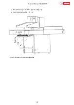
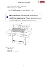
1. Set the main switch 1 to "ON" 1 position (Fig. 15)
2. Press the green button 2 (Fig.15)
- LED 3 lights up green
- the green OSSD 1 LED lights up (Fig.11) in the receiver 4 (Fig.15)
INFO
If after turning on the power supply with the main switch 1 (Fig. 15) and
pressing the green button 2, the LED 3 is green, the connection is correct
(correct direction of rotation), if the LED is red, the connection is not correct
and should be replaced in the plug two of three phase conductors.
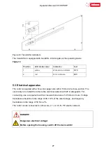
Figure 16 Light curtain
1. Transmitter
2. Receiver
A - field of the security curtain
Summary of Contents for INT-GU-07310EPSHP
Page 5: ...Operation Manual 7310 EPSHP 5 EC Conformity Declaration...
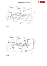
Page 42: ...Operation Manual 7310 EPSHP 42 Figure 26 Figure 27...
Page 55: ...Operation Manual 7310 EPSHP 55 Figure 43 Adjusting elements of backguage...
Page 61: ...Operation Manual 7310 EPSHP 61 Figure 50 Lubrication point of the knife assembly lever...
Page 66: ...Operation Manual 7310 EPSHP 66 PROGRAM MODULE OPERATOR MANUAL DOP B07S410 7...

