Operation Manual 7310 EPSHP
51
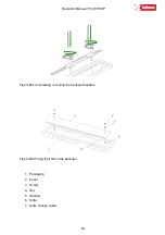
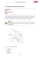
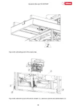
8.2.1 Lift the cutting stick 1 with a screwdriver 4 (fig. 37)
8.2.2 Rotate or replace the cutting stick
8.2.3 Insert the replaced stick into the channel between the tables 2 and place it on the dowel
3 (Fig. 37)
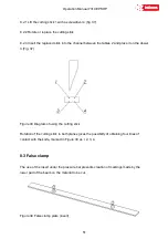
Figure 38 Diagram of using the cutting stick
Rotation of the cutting stick in both planes gives the possibility of obtaining four lines of
contact with the knife, marked in Figure 38 as l, 2, 3, 4.
8.3 False clamp
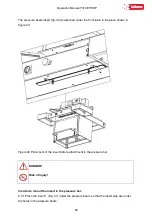
The use of the insert under the pressure bar prevents creation of markings made by the
lower part of the beam on the material to be cut.
Figure 39 False clamp plate (insert)
Summary of Contents for INT-GU-07310EPSHP
Page 5: ...Operation Manual 7310 EPSHP 5 EC Conformity Declaration...
Page 42: ...Operation Manual 7310 EPSHP 42 Figure 26 Figure 27...
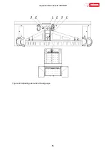
Page 55: ...Operation Manual 7310 EPSHP 55 Figure 43 Adjusting elements of backguage...
Page 61: ...Operation Manual 7310 EPSHP 61 Figure 50 Lubrication point of the knife assembly lever...
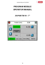
Page 66: ...Operation Manual 7310 EPSHP 66 PROGRAM MODULE OPERATOR MANUAL DOP B07S410 7...

