Operation Manual 7310 EPSHP
26
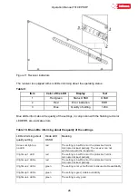
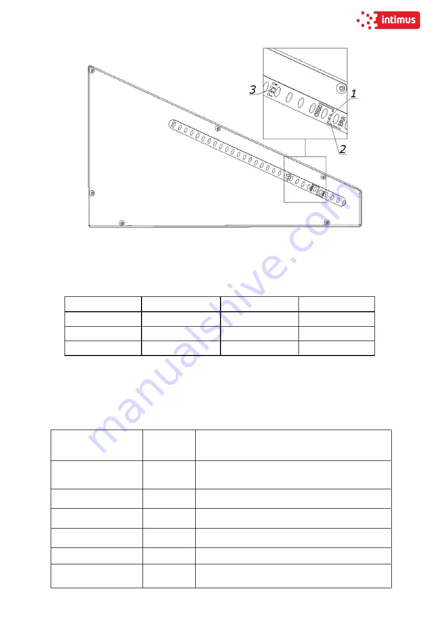
Figure 11 Receiver indicators
The receiver is equipped with six LEDs informing about the operating status:
Table 9:
Item
Color of the LED
Display
Text
1
Red/green
Status OSSD
OSSD
2
Red
Error indication
ERR
3
Blue
Quality of setting
1234
Blue LEDs inform about the quality of the settings, in conjunction with the flashing red color
LED ERR, also indicate errors.
Table 10. Blue LEDs informing about the quality of the settings
LEDs informing about
quality setting
Diode LED
OSSD
Meaning
It does not light up
no LED
red
The setting is insufficient or the protective field is
interrupted at least partially. The receiver can not
synchronize with the transmitter.
It lights up 1 LED
red
The setting is insufficient or the protective field is
interrupted at least partially.
It lights up 2 LEDs
red
The setting is insufficient or the protective field is
interrupted at least partially.
It lights up 2 LEDs
green
The setting is not yet sufficient to ensure stable availability
It lights up 3 LEDs
green
The setting is good, stable availability
It lights up 4 LEDs
green
The setting is very good
Summary of Contents for INT-GU-07310EPSHP
Page 5: ...Operation Manual 7310 EPSHP 5 EC Conformity Declaration...
Page 42: ...Operation Manual 7310 EPSHP 42 Figure 26 Figure 27...
Page 55: ...Operation Manual 7310 EPSHP 55 Figure 43 Adjusting elements of backguage...
Page 61: ...Operation Manual 7310 EPSHP 61 Figure 50 Lubrication point of the knife assembly lever...
Page 66: ...Operation Manual 7310 EPSHP 66 PROGRAM MODULE OPERATOR MANUAL DOP B07S410 7...

