25
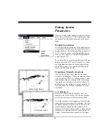
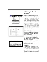
the Transducer Level correction should be
10 degrees
DOWN
. If the bottom slopes downward, adjust the
Transducer Level in the UP direction to compensate.
After setting the Transducer Level, view the VERT
display to verify the correction.
Align Adjustment
In case the horizontal scanning transducer has been
mounted such that it points in a direction other than
dead ahead, PC/View can compensate for up to 14
degrees of misalignment in either the port or star-
board direction.
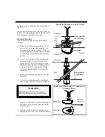
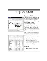
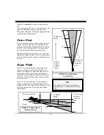
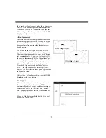
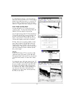
To set the Transducer Align correction, point the
boat directly toward a target (such as a piling, etc.)
The target should appear at the center of the horizon-
tal scanning display. If, however, the target is off to
the port (as shown on the “Before Align Adjust” pic-
ture at right), it means that the transducer was
mounted pointing slightly in the starboard direction.
If the target is offset to the port by 7 degrees, the
Transducer Align correction should be
7 degrees
Stbd
. If the target appears off to the right (Stbd),
adjust to the Port direction to bring the target back to
the center position.
After setting the Transducer Align, view the HORZ
display to verify the correction.
Keel Offset
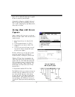
If the transducer(s) are mounted in a position above
the deepest point of your boat’s keel, PC/View can
automatically adjust the depth scale bars to compen-
sate for the offset. This will allow you to always
work with depths that are relative to the bottom of
your boat’s keel.
Move the slide bar to specify the depth of the keel
beneath the transducer(s).
After
Align
Adjust
Before
Align
Adjust
Summary of Contents for PC/View
Page 1: ...INTERPHASE INTERPHASE PC VIEW for Windows OPERATION MANUAL...
Page 54: ...54 W Warranty 6 7 55 Z Zoom 33...
Page 56: ...56...

