38
R05
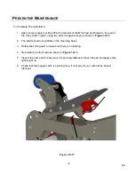
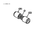
Figure 10-16
P
REVENTIVE
M
AINTENANCE
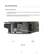
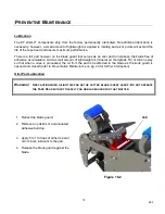
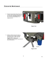
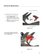
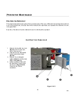
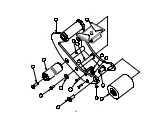
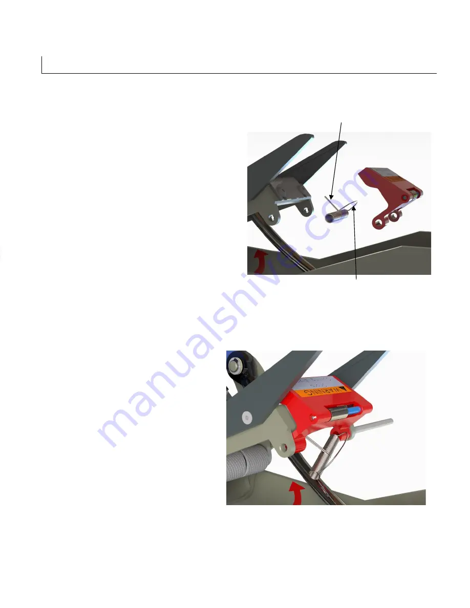
To properly position the new knife spring
1. Position the new knife spring as
shown in
Figure 10-15.
2. Note which leg of the spring should
lie behind the cutter blade mounting
plate.
3. Note that the looped leg shall wrap
around the blade guard.
Insert the cross shaft through the knife
arm, knife guard and knife guard spring as
shown in
Figure 10-16.
Behind The Cutter Blade Mounting
In Front Of Knife Guard
Figure 10-15
Summary of Contents for ET xtreme Series
Page 1: ...1 R05 ET xtreme STANDARD TAPE HEAD Serial Numbers UH230T UH430T ...
Page 2: ...2 R05 ...
Page 10: ...10 R05 SPECIFICATIONS UUUTape Head Dimensions Figure 6 1 ...
Page 11: ...11 R05 SPECIFICATIONS UUU Tape Head Components Figure 6 2 ...
Page 43: ...43 R05 THIS PAGE INTENTIONALLY LEFT BLANK ...
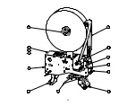
Page 44: ...4 6 10 8 1 9 3 5 7 2 11 12 13 44 ...
Page 46: ...1 15 2 3 6 10 12 14 7 11 8 9 5 4 16 14 13 13 4 18 17 46 ...
Page 48: ...6 11 8 14 2 12 9 7 10 5 3 3 13 48 ...
Page 50: ...6 7 15 11 10 14 4 2 9 3 5 13 12 8 1 16 50 ...
Page 52: ... 8 8 ...
Page 53: ... 7 0 3 57 6 5 37 21 8 47 8 47 83 8 52 5 83 2035 66 21 635 1 83 8 52 5 ...
Page 54: ...2 4 1 5 3 54 ...
Page 56: ... 8 8 ...
Page 58: ... 86 86 ...
Page 60: ...2 4 1 3 5 6 5 60 ...
Page 62: ...2 3 6 5 1 8 4 12 9 7 9 10 11 62 ...
Page 64: ...5 15 7 6 12 2 14 4 3 13 10 8 9 1 11 16 64 ...
Page 66: ...3 1 2 2 1 3 Standard Tape Head Mirror Tape Head 66 ...
Page 68: ...5 2 10 4 11 3 8 6 7 1 9 12 68 ...
Page 70: ...1 3 2 70 ...
Page 72: ... 8 8 ...
Page 74: ...6 1 2 5 3 4 74 ...
Page 76: ...19 4 9 16 6 7 5 8 1 11 3 10 14 12 15 13 18 17 2 20 76 ...
Page 78: ...1 2 No Tape options are available 78 ...

