32
R05
P
REVENTIVE
M
AINTENANCE
UUU
Application Roller Replacement
These blue rollers are wear items and should be inspected regularly and replaced if necessary.
Front & Rear Urethane Roller Replacement
Removing The Urethane Roller
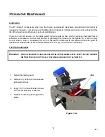
1. Using two allen keys, remove the M6 screws.
2. Application of heat may be required to break loose
from the threading agent. When one of the M6
screws comes out, insert a 5 mm allen key into its
place, thereby locking down the shaft.
3. Now one can proceed to remove the other screw.
4. Remove the PTFE washer and spring washer.
5. Remove the front roller hub.
6. With a sharp utility knife, cut away the blue
urethane roller from its roller core.
Installing The New Urethane Roller
1. Moisten the roller core’s outside and the urethane
roller’s inside by applying soapy water or foam.
2. Feed the urethane roller onto the end of the roller
core. The closed air pocket will help the urethane
tube to hop over the core.
3. Press the urethane roller until it reaches the roller
core’s rim/shoulder. (do not exert excessive force
so that the rim would crack)
4. Place roller back onto the shaft, rimmed side
closer to main frame.
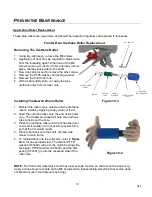
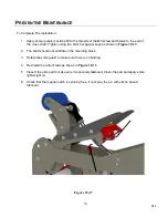
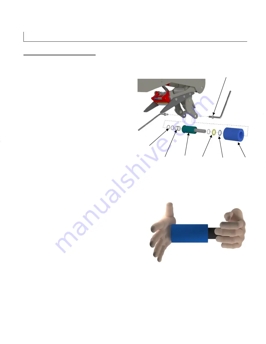
5. To reinstall back into the roller arm, refer to
Figure
10-3.
for an exploded view. The smaller PTFE
washer (UF6402) will go to the clutch bearing side,
the bigger PTFE washers (UF6335) and the disc
spring (UF4401) go into the recessed side of the
roller core.
NOTE:
The front roller assembly should have just enough tension, so that it is not free spinning.
Apply a drop of purple Loctite on the M6 Screws when reassembling. Ascertain that Loctite does
not bleed out (as it could prevent spinning).
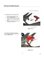
M6 –SCREW
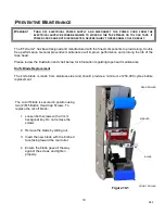
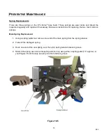
Figure 10-4
URETHANE
BLUE ROLLER
ROLLER
CORE
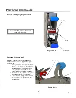
PTFE WASHER
UF6402
SPRING
WASHER
Figure 10-3
PTFE WASHER
UF6335
SPRING
Summary of Contents for ET xtreme Series
Page 1: ...1 R05 ET xtreme STANDARD TAPE HEAD Serial Numbers UH230T UH430T ...
Page 2: ...2 R05 ...
Page 10: ...10 R05 SPECIFICATIONS UUUTape Head Dimensions Figure 6 1 ...
Page 11: ...11 R05 SPECIFICATIONS UUU Tape Head Components Figure 6 2 ...
Page 43: ...43 R05 THIS PAGE INTENTIONALLY LEFT BLANK ...
Page 44: ...4 6 10 8 1 9 3 5 7 2 11 12 13 44 ...
Page 46: ...1 15 2 3 6 10 12 14 7 11 8 9 5 4 16 14 13 13 4 18 17 46 ...
Page 48: ...6 11 8 14 2 12 9 7 10 5 3 3 13 48 ...
Page 50: ...6 7 15 11 10 14 4 2 9 3 5 13 12 8 1 16 50 ...
Page 52: ... 8 8 ...
Page 53: ... 7 0 3 57 6 5 37 21 8 47 8 47 83 8 52 5 83 2035 66 21 635 1 83 8 52 5 ...
Page 54: ...2 4 1 5 3 54 ...
Page 56: ... 8 8 ...
Page 58: ... 86 86 ...
Page 60: ...2 4 1 3 5 6 5 60 ...
Page 62: ...2 3 6 5 1 8 4 12 9 7 9 10 11 62 ...
Page 64: ...5 15 7 6 12 2 14 4 3 13 10 8 9 1 11 16 64 ...
Page 66: ...3 1 2 2 1 3 Standard Tape Head Mirror Tape Head 66 ...
Page 68: ...5 2 10 4 11 3 8 6 7 1 9 12 68 ...
Page 70: ...1 3 2 70 ...
Page 72: ... 8 8 ...
Page 74: ...6 1 2 5 3 4 74 ...
Page 76: ...19 4 9 16 6 7 5 8 1 11 3 10 14 12 15 13 18 17 2 20 76 ...
Page 78: ...1 2 No Tape options are available 78 ...

