35
R05
P
REVENTIVE
M
AINTENANCE
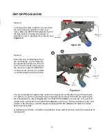
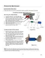
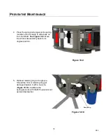
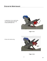
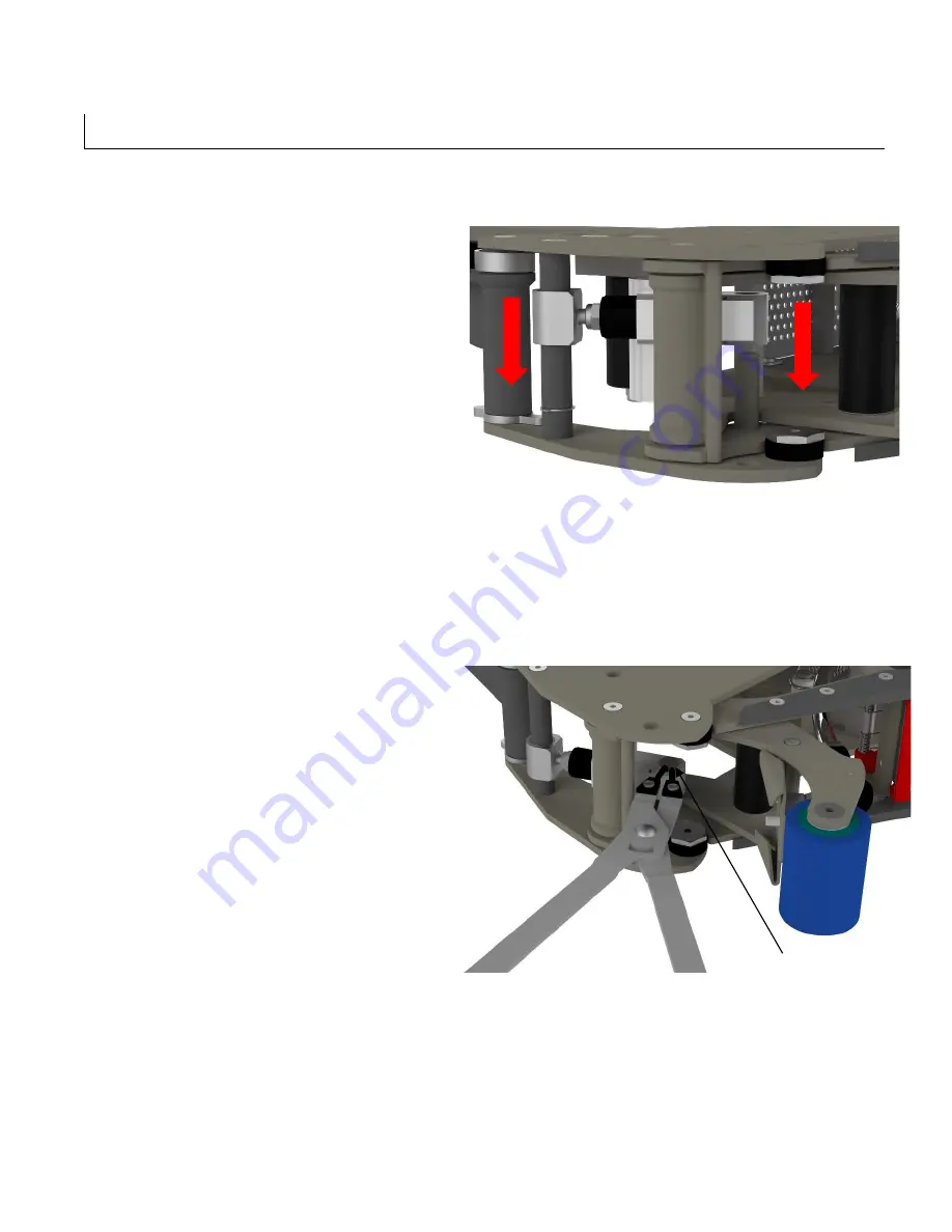
4. Press the spring barrel against the spring
mandrel until it is ready to slide back on
the short shaft.
See Figure 10-9.
Move
the whole sub assembly back to its
original position.
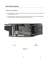
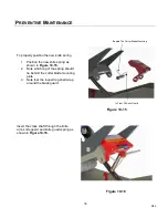
5. Reinsert retaining ring to the groove.
Should the 10 mm retaining ring get
damaged replace it with a new one.
(
Figure 10-10
.) Calibrate the
spring pressure with the M6 nylon lock nut
as described earlier.
Snap Ring
Figure 10-9
Figure 10-10
Summary of Contents for ET xtreme Series
Page 1: ...1 R05 ET xtreme STANDARD TAPE HEAD Serial Numbers UH230T UH430T ...
Page 2: ...2 R05 ...
Page 10: ...10 R05 SPECIFICATIONS UUUTape Head Dimensions Figure 6 1 ...
Page 11: ...11 R05 SPECIFICATIONS UUU Tape Head Components Figure 6 2 ...
Page 43: ...43 R05 THIS PAGE INTENTIONALLY LEFT BLANK ...
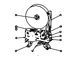
Page 44: ...4 6 10 8 1 9 3 5 7 2 11 12 13 44 ...
Page 46: ...1 15 2 3 6 10 12 14 7 11 8 9 5 4 16 14 13 13 4 18 17 46 ...
Page 48: ...6 11 8 14 2 12 9 7 10 5 3 3 13 48 ...
Page 50: ...6 7 15 11 10 14 4 2 9 3 5 13 12 8 1 16 50 ...
Page 52: ... 8 8 ...
Page 53: ... 7 0 3 57 6 5 37 21 8 47 8 47 83 8 52 5 83 2035 66 21 635 1 83 8 52 5 ...
Page 54: ...2 4 1 5 3 54 ...
Page 56: ... 8 8 ...
Page 58: ... 86 86 ...
Page 60: ...2 4 1 3 5 6 5 60 ...
Page 62: ...2 3 6 5 1 8 4 12 9 7 9 10 11 62 ...
Page 64: ...5 15 7 6 12 2 14 4 3 13 10 8 9 1 11 16 64 ...
Page 66: ...3 1 2 2 1 3 Standard Tape Head Mirror Tape Head 66 ...
Page 68: ...5 2 10 4 11 3 8 6 7 1 9 12 68 ...
Page 70: ...1 3 2 70 ...
Page 72: ... 8 8 ...
Page 74: ...6 1 2 5 3 4 74 ...
Page 76: ...19 4 9 16 6 7 5 8 1 11 3 10 14 12 15 13 18 17 2 20 76 ...
Page 78: ...1 2 No Tape options are available 78 ...

