BELL SYSTEM PRACTICES
AT&TCo Standard
SECTION 574-504- 72 0
Issue 1, July 1981
43 5-LEVEL PAPER TAPE UNIT
DISASSEMBLY/REASSEMBLY
CONTENTS
PAGE
1.
GENERAL .....................
1
2. TOOLS REQUIRED ..............
2
3.
DISASSEMBLY/REASSEMBLY .....
2
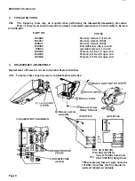
Replace of Fuses and Access
to Variable Feature Switches ........
2
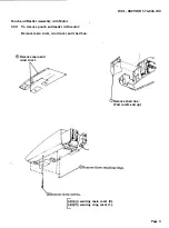
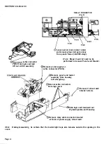
Punch and Reader Assembly
with Motor .....................
3
41 071 1 Logic Card ...............
5
Power Supply and Rear
Frame Assembly .................
5
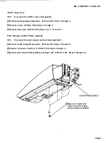
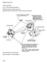
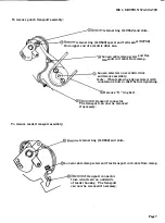
Transport Assemblies .............
6
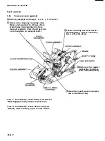
Punch Assembly .................
8
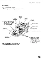
Reader Assembly .................
9
1. GENERAL
1.01
The procedures provided in this section
break the PTU down into subcomponents.
The appropriate parts sections illustrate the
arrangement of subcomponents and parts.
Caution:
Remove all power from the
PTU
before performing any component replacement.
1.02
Whenever this section is reissued, the
reason for reissue will be listed in this
paragraph.
-1.-03
Wlien remoVing a major
or
part from the PTU, do not pry or force
parts to provide the necessary clearance for
removal. Follow the removal procedure and note
how each part is removed and the sequence of its
removal so that proper reassembly can be accom -
plished. For reassembly, reverse the removal
procedure except where different instructions
are given.
1.04 Reference in the procedures to left and
right and up or down and top or bottom,
etc, refer to the paper tape unit in its normal
operating position.
1.05
Refer to Maintenance Tools, Section
570-005-800 for a complete listing of
the various types of hand tools available for main
tenance of Teletype Corporation equipment. For
·
a listing of the tools required to perform the
disassembly /reassembly
procedures,
refer
to
2. TOOLS REQUIRED.
1.06 All ordering numbers shown in this manual
are Teletype Corporation part numbers.
1.07 Some parts that are not listed in the parts
index are shown as necessary to the dis
assembly procedures such as screws, ring retain
ers, etc. Most of these parts are common to other
Teletype Corporation product lines and, if
needed, may already
be
available in field repair
kits or can be ordered.
1.08 Containers and packing materials retained
from maintenance spares should be saved
and reused when returning defective components
foi repair.
1.09 Adjustment information is provided in
Punch Unit adjustments and Spring Ten
sions, Section 57 4-505-700, and Reader Unit
-and-
Spring_
�ction
574-506-700.
Note:
When ordering replaceable components,
unless otherwise specified, prefix each part
number with the letters "TP" (ie, TP 41 02 05).
Prepared for American Telephone and Telegraph Company by Teletype Corporation
©
1981 by Teletype Corporation -
All
rights reserved
Printed in U.S.A.
Pagel


