background image

ISS 1, SECTION 574-504-720 

410711  Logic Card 

3.03 

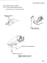
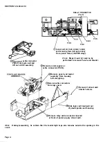
To remove  the 410711logic  card assembly: 

(!)Remove bustle and guard assembly.  Perform 3.01,  Steps 1  through 4. 

®Remove  covers.  Perform 3.02,  Steps 1  through 4. 

@Remove logic  card.  Perform 3.02,  Steps 5, 

6, 

7, 11  and 12. 

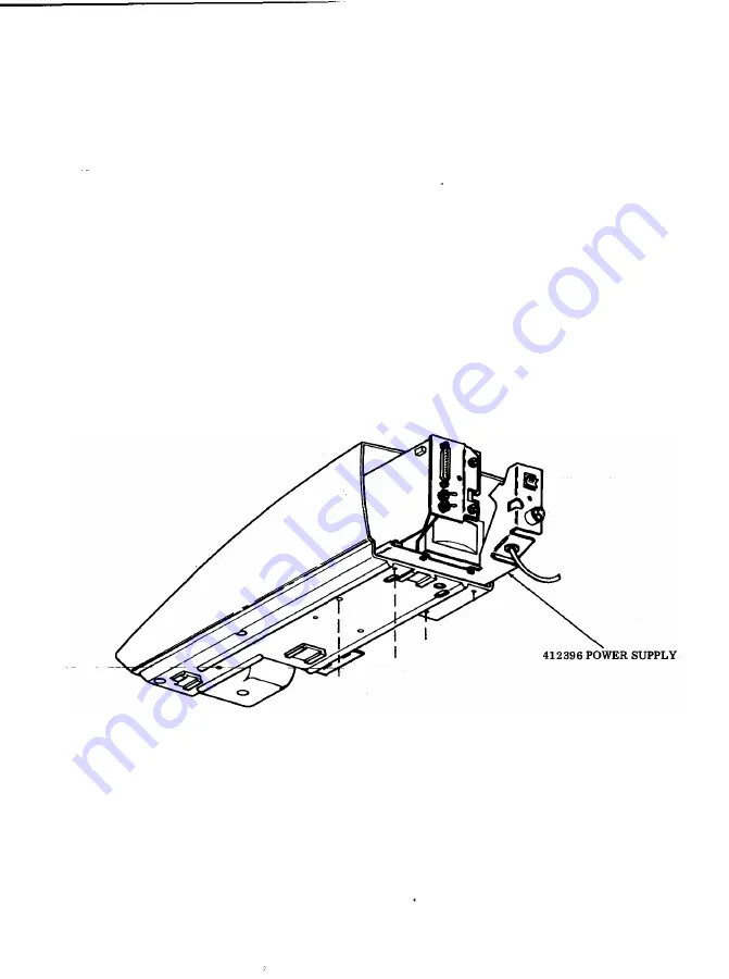
Power  Supply  and  Rear  Frame Assembly 

3.04 

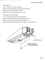
To remove  the power  supply  and  rear frame assembly: 

_(!)Remove  bustle  and  guard  assembly.  Perform 3.01,  Steps 1  through 4. 

Remove  covers  and  chad  box.  Perform 3.02,  Steps 1  through 4. 

@Remove  punch and reader  assembly  and logic  card.  Perform  3.02,  Steps 5  through 12. 

,.) 

J-....-

....- /"" 

· 

0Remove 4  screws  and 

slide out  power supply 

and  rear frame assembly. 

® 

Page 5 

Summary of Contents for 43

Page 1: ...eft and right and up or down and top or bottom etc refer to the paper tape unit in its normal operating position 1 05 Refer to Maintenance Tools Section 570 005 800 for a complete listing of the various types of hand tools available for main tenance of Teletype Corporation equipment For a listing of the tools required to perform the disassembly reassembly procedures refer to 2 TOOLS REQUIRED 1 06 ...

Page 2: ...es TOOLS Hex key wrench 1 16 inch Hex key wrench 050 Hex key wrench 093 Screwdriverjw clip 1 4 inch Assembly wrench 1 4 inch Wrench 3 16 x 1 4 open end Wrench 5 16 x 3 8 open end Wrench 7 16 x 1 2 open end 3 01 To replace fuses or gain access to variable feature switches VARIABLE FEATURE SWl l GH Page 2 Remove screws and plate LOGIC SWITCHES 412349 Remove screws Early Version F2 F3 F4 NEW STYLE 0 ...

Page 3: ...eader Assembly with Motor 3 02 To remove punch and reader with motor Remove main cover wind cover and chad box Remove main and wind cover 1 lRemove chad box Pull to left and up 143o618 securing main cover 2 0675 securing wing cover 1 Page3 ...

Page 4: ...o remove Punch and Reader Remove power supply ac cable connector P 601 Remove punch and reader assembly from housing Lift straight up Remove cable connectors from logic card Remove 2 circuit card bracket screws J Slide logic card rearward out of plastic guides and housing 9 Remove relay cable connector located at front of power supply circuit card Note During reassembly be certain that the reader ...

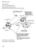
Page 5: ... 3 02 Steps 5 6 7 11 and 12 Power Supply and Rear Frame Assembly 3 04 To remove the power supply and rear frame assembly _ Remove bustle and guard assembly Perform 3 01 Steps 1 through 4 0Remove covers and chad box Perform 3 02 Steps 1 through 4 Remove punch and reader assembly and logic card Perform 3 02 Steps 5 through 12 I I I t y I J l 0Remove 4 screws and V slide out power supply and rear fra...

Page 6: ...flat washer 156572 and felt washer 95758 from end of connector link 2 Pis and remove connector link TRANSPORT DRIVE ECCENTRIC ASSEMBLY 4 Remove outer retainer ring 119649 and felt washer 169654 in front of pawl Remove inner retainer ring 119649 pawl and pawl spring take care not to lose spring Note When replacing carefully compress spring in hole as pawl is moved onto post in front of spring Steps...

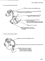
Page 7: ...tric drive and remove assembly Note When replacing align setscrew with countersunk hole in shaft before tightening To remove reader transport assembly sJRemove 0 ring belt 11JDisconnect transport connector The transport can now be removed if necessary Remove retainer ring 119652 and shim 131 Loosen cable clamp screw and free transport coil cable from clamp 4JDisconnect transport connector from cir...

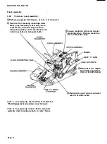
Page 8: ... be taken not to lose shims on transport shaft Note 1 In reassembly the Feed Pawl and Ratchet Wheel Engagement adjustment must be made Note 2 In reassembly connect link to transport assembly while mounting punch to center frame PageS Loosen mounting screw and remove grounding strap Remove mounting screw with cable clamp FRAME BELT O RING 0Disconnect two magnet bank cable connectors Part of 412325 ...

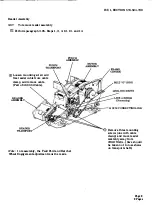
Page 9: ...able Part of 412324 Cable READER ASSEMBLY PUNCH ASSEMBLY Note In reassembly the Feed Pawl and Ratchet Wheel Engagement adjustment must be made ISS 1 SECTION 574 504 720 L 7 0 412250 CONNECTING LINK 31 Remove three mounting screws one with cable clamp and move reader assembly away from cenJeJ frllJl1e _Care should be taken not to lose shiins on transport shaft Page9 9 Pages ...

Reviews:

Related manuals for 43