


Section 7, Plumbing the System
International Thermal Research
7-7
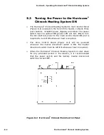
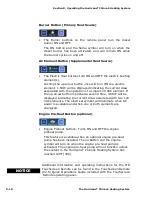
Figure 7-4 Potable Hot Water System Plumbing
7.6 Engine Plumbing Installation
To make use of engine waste heat; hot coolant from the engine
enters the Hurricane
®
Chinook at the “Engine Supply” connection
and returns to the engine from the “Engine Return” connection.
The Engine Heat Supply/Return connections are located on the top
(towards the back) of the Hurricane
®
Chinook. These connection
points are 1/2" hose.. If 1/2" or 3/4” hose is used, 1/2” to 1/2" or
1/2” to 3/4" barb fittings can be used to make the connection to the
engine.
See
Sec
. 8,
Fig. 8-3, for location of the mixing valve.
If the optional engine pre-heat function is required, an additional
pump is installed (outside the Hurricane
®
Chinook) to move the
engine coolant through the engine when it’s not running. The engine
pre-heat pump is wired to the free pair of wires extending from the
center wiring harness strain relief on top of the heater. The engine
pre-heat pump wire-pair is indicated as such with yellow heat
shrink. See
Sec. 6, Figure 6-1,
for wiring the engine pre-heat pump.
The pre-heat switch on the Remote Operating Panel will activate this
pump.


