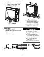
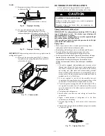
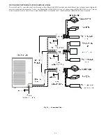
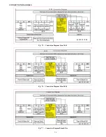
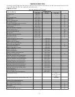
International comfort products DLCBHR Installation Instructions Manual Download Page 40

40

TROUBLESHOOTING

This unit has on- board diagnostics. Error codes are displayed on the wired remote controller and the outdoor unit microprocessor board with
colored LED lights. The table below explains the error codes on both.

SIZES 48 - 56

Table 29—Malfunction Status Table

Errors of definition

Main control display for outdoor unit

Indoor unit code Testing board

code

Yellow LED

Red LED

Green LED

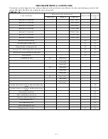
The compressor is start up

Flash 1 time

IPM current protection

Flash 3 times

H5

H5

IPM temperature protection

Flash 5 times

P8

P8

PFC current protection

Flash 7 times

HC

HC

PFC temperature protection

Flash 8 times

P8

P8

Low voltage protection

Flash 9 times

PL

PL

High voltage protection

Flash 10 times

PH

PH

Low pressure protection

Flash 11 times

E3

E3

High pressure protection

Flash 12 times

E8

E8

High pressure switch protection

Flash 13 times

E1

E1

Capacitor charging error

Flash 14 times

PU

PU

Current protection

Flash 15 times

E5

E5

Memory card error

Flash 16 times

EE

EE

Compressor demagnetizing protection

Flash 17 times

HE

HE

Compressor de- synchronizing

Flash 18 times

H7

H7

Compressor phase lack

Flash 19 times

U2

U2

Compressor phase circuit detection error

Flash 20 times

U1

U1

Compressor current protection

Flash 21 times

L9

L9

Compressor overload protection

Flash 22 times

H3

H3

Compressor discharge temperature protection

Flash 23 times

E4

E4

Lack of refrigerant or jam protection

Flash 31 times

F0

F0

Normal operation

Flash 1 time

Frequency limitation for current protection

Flash 2 times

F8

Oil returning mode

Flash 3 times

F7

F7

Defrosting mode

Flash 4 times

H1

H1

Frequency limitation for IPM temperature protection

Flash 5 times

EU

EU

Frequency limitation for PFC temperature protection

Flash 6 times

EU

EU

Frequency limitation for compressor overload protection

Flash 8 times

LU

Frequency limitation for discharge temp. protection

Flash 9 times

F9

Frequency limitation for low pressure protection

Flash 10 times

Pn

Frequency limitation for high pressure protection

Flash 11 times

F6

F6

Discharge temperature sensor error

Flash 12 times

F5

F5

Outside temperature sensor error

Flash 13 times

F3

F3

Suction temperature sensor error

Flash 15 times

dc

Condenser temperature sensor error

Flash 16 times

A7

A7

Sub- cool temperature sensor error

Flash 17 times

bC

Low pressure sensor error

Flash 18 times

dL

High pressure sensor error

Flash 19 times

e1

Fan motor protection

Flash 20 times

H6

H6

Driving board is connected

Flash 1 time

Testing board is connected

Flash 2 times

Computer is connected

Flash 4 times

Indoor unit 1 is connected

Flash 5 times

Indoor unit 2 is connected

Flash 6 times

Summary of Contents for DLCBHR

Page 1: ...SIDERATIONS 2 GENERAL 2 SYSTEM REQUIREMENTS 3 4 ELECTRICAL DATA 4 PARTS LIST 6 DIMENSIONS 7 14 CLEARANCES 15 17 DIMENSIONS BRANCH BOXES 18 19 INSTALLATION GUIDE 20 HIGH WALL INDOOR UNIT INSTALLATION 2...

Page 2: ...ese words are used with the safety alert symbol DANGER identifies the most serious hazards which will result in severe personal injury or death WARNING signifies hazards which could result in personal...

Page 3: ...Size Suction In 1 2 1 2 5 8 5 8 Table 4 Indoor Cassette Indoor Cassette Size 12 18 24 Pipe Connection Size Liquid In 1 4 1 4 3 8 Pipe Connection Size Suction In 3 8 1 2 5 8 Table 5 Indoor Ducted Indoo...

Page 4: ...OOR FAN VOLT PHASE HZ MAX MIN V PH HZ FLA HP W 9 208 230 1 60 253 187 208 230 1 60 0 28 1 24 80 12 0 31 1 18 80 18 0 41 1 12 100 21 0 5 1 36 124 24 0 5 1 36 124 Table 12 Floor Console UNIT SIZE System...

Page 5: ...ion Method for Power and Communication Wiring To minimize communication wiring interference Power Wiring The main power is supplied to the outdoor unit The field supplied power wiring from the outdoor...

Page 6: ...control 1 Battery 1 5V 2 GasketM6X 18X1 4 4 GasketM10X 30X2 5 10 Screw ST4 8X13 HC 4 Screw M6X25 4 Nut of Connector Pipe B Package 1 Pipe Connection Nut I shape 1 Connection wire of wired control 1 Wi...

Page 7: ...Table 14 High Wall DLFAHH Dimensions Unit Size W In mm D In mm H In mm Q In mm Operating Weight Lbs kg 9k 37 8 960 g 8 07 205 12 6 320 2 16 55 33 07 15 12k 37 8 960 8 07 205 12 6 320 2 16 55 33 07 15...

Page 8: ...OOR CONTINUED Fig 3 Wall Dimensions Table 15 High Wall DLFBHB Unit Size W In mm D In mm H In mm Operating Weight 9k 34 09 8 23 11 5 24 3 12k 34 09 8 23 11 5 24 3 18k 40 079 9 055 12 6 30 9 24 46 378 1...

Page 9: ...9 DIMENSIONS INDOOR CONTINUED Fig 4 Cassette Grill Dimensions Fig 5 Cassette Side View Dimensions...

Page 10: ...10 DIMENSIONS INDOOR CONTINUED Fig 6 Cassette Connection Side View Dimensions Fig 7 Cassette Top View Dimensions...

Page 11: ...in 615 mm 30 4 5 in 782 mm 6 1 7 in 156 mm 7 7 8 in 200 mm 25 in 635 mm 12 18 37 in 942 mm 19 1 3 in 491 mm 34 in 862 mm 32 2 7 in 820 mm 35 3 7 in 900 mm 24 1 5 in 615 mm 38 2 3 in 982 mm 6 1 7 in 15...

Page 12: ...12 DIMENSIONS INDOOR CONTINUED Fig 9 Floor Console Dimensions...

Page 13: ...13 DIMENSIONS OUTDOOR Fig 10 Outdoor Dimensions Size 18 Fig 11 Outdoor Dimensions Size 24...

Page 14: ...14 DIMENSIONS OUTDOOR CONTINUED Fig 12 Outdoor Dimensions Size 30 42 Fig 13 Outdoor Dimensions Size 48 56...

Page 15: ...15 CLEARANCES INDOOR 6 0 15m min 5 0 13m min 6 5 0 13m min 1 8m CEILING FLOOR Fig 14 High Wall Clearance Fig 15 Cassette Clearance...

Page 16: ...16 CLEARANCES INDOOR CONTINUED Fig 16 Ducted clearance Fig 17 Floor console clearance...

Page 17: ...ES OUTDOOR CONTINUED A D B Air outlet Air inlet C E Fig 18 Clearances Outdoor 18 42 Table 17 Clearances Outdoor UNIT Minimum Value in mm A 24 609 B 24 609 C 24 609 D 4 101 E 4 101 Fig 19 Clearances Ou...

Page 18: ...26 mm 3 4 7 in 91 mm 3 1 7 in 80 mm 2 2 5 in 61 mm 3 1 2 in 88 mm 7 1 6 in 182 mm 3 1 3 in 85 mm 2 1 2 in 64 mm Fig 20 Outline Dimensions Table 18 Outline Dimensions Sorts Indoor unit side inch mm Out...

Page 19: ...1 2 in 64 mm 13 8in 35mm 23 4in 70mm 23 4in 70mm 1 4 5in 35mm 23 4in 70mm 23 4in 70mm Fig 22 Outline Dimensions Table 20 Outline Dimensions Sorts Indoor unit side inch mm Outdoor unit side inch mm Po...

Page 20: ...WALL FOR INTERCONNECTING PIPING DRAIN AND WIRING Refrigerant Line Routing The refrigerant lines may be routed in any of the four directions shown in Fig 24 a and b For maximum serviceability it is re...

Page 21: ...shown in Fig 28 48mm Fig 28 Install the indoor unit S Prior to the installation make a good preparation for all piping refrigerant pipe drain pipe and wiring wires of the wired controller wires betwee...

Page 22: ...r Supply Outlet Return Air Inlet Size A B C D 09 6 1 7 in 156 mm 26 in 662 mm 22 5 6 in 580 mm 22 5 6 in 580 mm 12 18 6 1 7 in 156 mm 34 in 862 mm 30 5 7 in 780 mm 6 3 8 in 162 mm 21 6 1 7 in 156 mm 4...

Page 23: ...ose INSTALLATION OF THE DRAIN PIPE 1 The diameter of the drain pipe should be larger than or equal to that of the refrigerant pipe PVC pipe outer dimater 1 in 25 mm wall thickness 0 06 in 1 5 mm 2 The...

Page 24: ...ll in areas with or near an abundance of oil S Do not install in areas with an acid base area S Do not install in areas with an irregular electrical supply Indoor Unit Installation Drawings The indoor...

Page 25: ...e 2 Insert a wall pipe into the hole 3 Insert a wall cover into wall pipe Inside Outside Caulking Wall embedded pipe field supply Wall hole cover Wall embedded pipe field supply 2 1 6 in 55 mm Fig 48...

Page 26: ...ide casings 2 Upper casing 3 Side casings Remove the pillar Remove 7 screws Fig 51 Remove the screws For Side Piping S Remove the pillars 1 Remove the 7 screws 2 Remove the upper casing 2 tabs 3 Remov...

Page 27: ...downward so that the chips do not enter the pipe 3 Fit the flare nut on the pipe 4 Flare the pipe 5 Check that the flaring is properly made 1 DO not use mineral oil on flared part 2 Prevent mineral oi...

Page 28: ...and water pump in the dining room and kitchen which would reduce the capacity of heat exchanger lead water leakage and abnormal operation of the water pump The following treatment should be taken und...

Page 29: ...motor oil screw it by hand and then tighten with a spanner Refer to form 1 to check if the wrench had been tightened too tight would mangle the nut and lead leakage Examine the connection pipe to see...

Page 30: ...the impact fastener after the connection 2 Entwine the small sponge on the electric wire entwine to prevent condensation 3 Impact tightly with an impact fastener after connection Then fir on the elec...

Page 31: ...pen service valves or remove protective caps from tubing ends until all the connections are made S Bend tubing with bending tools to avoid kinks and flat spots S Keep the tubing free of dirt sand mois...

Page 32: ...on sizes 48 and 56 Separate power connection is required for the Outdoor unit and the Branch Boxes Refer to Branch Box installation instructions NOTE CAUTION EQUIPMENT DAMAGE HAZARD Failure to follow...

Page 33: ...es and nine different types of indoor units high wall cassette ducted and floor console At least one Branch Box KSAUI0201AAA up to 2 indoor units or KSAUI0401AAA up to 3 indoor units is required on th...

Page 34: ...34 CONNECTION DIAGRAMS 18 42 Fig 75 Connection Diagram Sizes 18 42 48 56 Fig 76 Connection Diagram Sizes 48 56 Connection Diagram Fig 77 Connection Diagram Branch Box...

Page 35: ...0 for each indoor unit SYSTEM VACUUM AND CHARGE UNIT DAMAGE HAZARD Failure to follow this caution may result in equipment damage or improper operation Never use the system compressor as a vacuum pump...

Page 36: ...inue operating for an additional 15 minutes 2 Close service valves and shut off vacuum pump 3 Connect a nitrogen cylinder and regulator to system and open until system pressure is 2 psig 4 Close servi...

Page 37: ...through which the cables and tubing pass INDOOR UNIT 1 Do all Remote Control buttons function properly 2 Do the display panel lights work properly 3 Does the air deflection louver function properly 4...

Page 38: ...ugh remote controller within 200s displayed directly on nixie tube after 200s P8 Refrigerant lacking or blockage protection of system not available for residential ODU F0 Charging malfunction of capac...

Page 39: ...tdoor ambient sensor malfunction Flash 6 times F3 Outdoor tube sensor malfunction Flash 5 times F4 Exhaust sensor malfunction Flash 7 times F5 Attain the temperature of switch on Flash 8 times Frequen...

Page 40: ...ent protection Flash 21 times L9 L9 Compressor overload protection Flash 22 times H3 H3 Compressor discharge temperature protection Flash 23 times E4 E4 Lack of refrigerant or jam protection Flash 31...

Page 41: ...12 times Indoor unit 9 is connected Flash 13 times Indoor anti freeze protection E2 E2 Inside temperature sensor error F1 F1 Evaporator midway temp sensor error F2 F2 Liquid pipe of BU module tempera...

Page 42: ...rature sensor error Flash 2 times b5 b5 indoor unit address Indoor unit B gas tube temperature sensor error Flash 3 times b7 b7 indoor unit address Indoor unit B liquid tube temperature sensor error F...

Reviews: