


23
INSTALLATION OF THE CONDENSATE PIPE
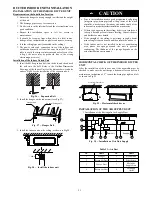
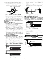
1. The condensate pipe should keep a inclination angle of 5 ~
10”, to facilitate the drainage of the condensate water. And
the joints of the condensate pipe should be insulated by the
insulation material to prevent condensing (see Fig. 36).
Insulating Layer for the Condensate Pipe
Pipe Lid
Fig. 36
-
Thermal Insulation of the Condensate Pipe
2. There is a condensate outlet on both the left and right sides of
the unit. Once one is confirmed for use, the other should be
clogged by a rubber plug, bundled by the binding wire and
insulated by the insulation material to avoid water leakage.
3. The right outlet is defaulted to be clogged with a plug.
IMPORTANT
: No water leakage is allowed on the joint of the
condensate pipe.
DESIGN OF THE DRAIN PIPE
1. The drain pipe should always be kept an inclination angle
(1/50~1/100) to avoid water from gathering.
2. During the connection of the drain pipe and device, do not
impose excessive force on the pipe on one side of the device.
Additionally the pipe should be secured closely to the device.
3. The drain pipe can be the ordinary hard PVC pipe which
can be purchased locally. During the connection, inset the
end of the PVC pipe to the drain outlet, then tighten it with
the drain hose and binding wire. Never connect the drain
outlet and the drain hose with adhesive.
4. When the drain pipe is used for multiple devices, the public
section of the pipe should be 4 in (100 mm) lower than the
drain hole of each device and it is better to use the much
thicker pipe for such a purpose.
INSTALLATION OF THE DRAIN PIPE
1. The diameter of the drain pipe should be larger than or
equal to that of the refrigerant pipe (PVC pipe, outer
dimater: 1 in (25 mm), wall thickness
0.06 in (1.5 mm).
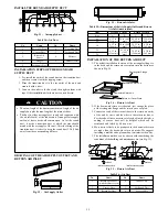
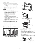
2. The drain pipe should be a short as possible and with at
least a 1/100 degree of slope to avoid forming air pockets.
3. If the proper degree of slope of the drain pipe is not
allowed, a lift pipe should be installed.
4. A distance of 3.28 ft~4.92 ft (1m~1.5 m) should be kept
between the hangers to avoid the drain hose from making a
turn.
3.28 ft~4.92 ft
(1m~1.5 m)
(Wrong)
Fig. 37
-
Slope Degree
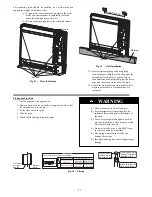
5. Insert the drain hose into the drain hole and tighten it with
clamps.
6. Wrap the clamps with large amount of sponge for thermal
insulation.
7. The drain hose inside the room also should be insulated.
Clamp (accessory)
Sponge (gray)
Drain Hose
Sponge (accessory)
Clamp
(accessory)
Max. 4mm
Fig. 38
-
Drain Hose Insulation
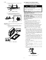
PRECAUTIONS FOR THE LIFT PIPE
The lift pipe install height should be less than 33 1/2 in (850 mm). We
recommend setting an inclination angle 1~ 2
_
for the lift pipe toward
the drainage direction. If the lift pipe and the unit form a right angle,
the height of the lift pipe must be less than 31 1/2 in (800 mm).
1°
2°
1~1.5m
1000mm
850mm
11 4/5 in (300 mm)
150mm
Ceiling
Clamp (accessory)
Drain Hose (accessory)
Lift Pipe
Hanger Bracket
Fig. 39
-
Installation Height
NOTE
:
1. The inclination height of the drain hose should be within 3
in. (75 mm) so that the outlet of the drain hose does not
suffer any external force.
2. If multiple drain pipes converge, follow the installation
steps below.
The specification of the joint of the drain pipe should be suitable to the running capacity of the unit
Drain Hose (accessory)
Max.75mm
Max.1000mm
Fig. 40
-
Multiple Line Convergence