


20
INSTALLATION GUIDE
Up to nine fan coil units can be connected to one outdoor unit.
Refer to the Product Data for approved combinations.
Ideal installation locations include:
Each Indoor Unit
S
A location where there are no obstacles near inlet and outlet area.
S
A location which can bear the weight of indoor unit.
S
Do not install indoor units near a direct source of heat such as
direct sunlight or a heating appliance.
S
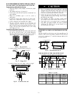
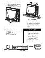
A location with the appropriate clearances (see Fig. 14).
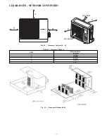
Outdoor Unit
S
A convenient location for the installation that is not exposed to
strong wind. If unit is exposed to strong winds it is recommended
that a field- fabricated wind baffle be used (see Fig. 73).
S
A location which can bear the weight of outdoor unit and where
the outdoor unit can be mounted in a level position.
S
A location which provides appropriate clearances (see Fig.
17
and Fig. 18).
S
Do not install the indoor or outdoor units in a location with
special environmental conditions. For those applications, contact
your Sales Representative.
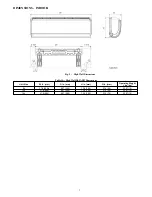
HIGH- WALL INDOOR UNIT
INSTALLATION
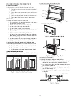
INSTALL MOUNTING PLATE
For each fan coil:
1. Carefully remove the mounting plate, which is attached to
the back of the indoor unit.
2. The mounting plate should be located horizontally and level
on the wall.
3. If the wall is block, brick, concrete or similar material, drill .2”
(5 mm) diameter holes and insert anchors for the appropriate
mounting screws.
4. Attach the mounting plate to the wall (see Fig. 2 and 3).
FOR EACH FAN COIL, DRILL HOLE IN WALL FOR
INTERCONNECTING PIPING, DRAIN AND WIRING
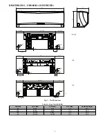
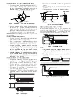
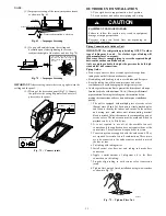
Refrigerant Line Routing
The refrigerant lines may be routed in any of the four directions
shown in Fig. 24 (a) and (b).
For maximum serviceability, it is recommended to have refrigerant
line flare connections and the drain connection on the outside of
the wall that the fan coil is mounted on.
1 Right Exit
2 Right Rear Exit
3
Left Exit
4
Left Rear Exit
( a )
( b )
( c )
As viewed from front
Knockout 3
Knockout 2
Knockout 1
A08281
Fig. 24
-
Refrigerant Line Routing
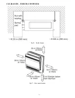
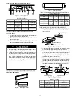
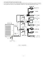
If piping is going through the back:
1. Determine pipe hole position using the mounting plate as a
template. Drill pipe hole diameter per chart below. The
outside pipe hole is 1/2- in. (13 mm) min. lower than inside
pipe hole, so it slants slightly downward (see Fig. 25).
If piping is going to exit from the left rear, it is
recommended to field- fabricate piping extensions to get the
flare connections to the outside of the wall.
1/2 in. (13 mm)
Min.
INDOOR
OUTDOOR
A07371
Fig. 25
-
Drill Holes
Table 22—Hole Diameter
Unit Size
Hole Diameter
in. (mm)
9k, 12k, 18k and 24k
3.75 (95)
If piping is going through the right or left side:
1. Use a small saw blade to carefully remove the
corresponding plastic covering on side panel and drill the
appropriate size hole where the pipe is going through the
wall (see Fig. 24 (c)).
2. Remove knockout 1 if you are running only the wiring.
Remove knockout 1 and 2 or knockout 1, 2 and 3 if you are
running both piping and wiring through the side of the unit.
DLFAHH Rear left condensate drain connection on
unit.
When piping out of the rear right, a field supplied joint
connection will need to be made behind the unit.
Please ensure that the connection is made properly to avoid
leaks.
CAUTION
!