


31
NOTE
:
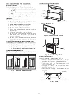
(1.) Improper screwing of the screws may cause issues
as shown in Fig. 69.
Air leak
Air leak from ceiling
Water condensatation, water drop
Fig. 69
-
Improper Screwing
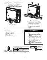
(2.) If a gap still exists between the ceiling and
decoration panel after tightening the screws,
readjust the height of the indoor unit (see Fig. 70).
If the raising lever and drain hose are
not affect, can adjust the height of
indoor unit by the hole on the corner
of panel.
Gaps are not allowed
Fig. 70
-
Improper Screwing
IMPORTANT
: After securing, ensure there is no gap between the
ceiling and the panel.
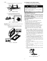
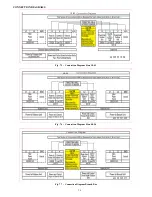
(3.) Wiring of the decoration panel (Fig.71). Connect
the joints for the swing flap motor lead wire (at 2
places) onto the panel.
At body
At pane
At body
At pane
Fig. 71
-
Connect joints
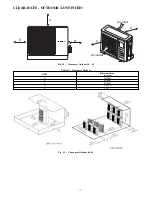
OUTDOOR UNIT INSTALLATION
1. Use a rigid base to support unit in a level position.
2. Locate outdoor unit and connect piping and wiring.
CAUTION
!
EQUIPMENT DAMAGE HAZARD
Failure to follow this caution may result in equipment
damage or improper operation.
Excessive torque can break flare nut depending on
installation conditions.
Piping Connections to Outdoor Unit
IMPORTANT
:
Use refrigeration grade tubing ONLY. No other
type of tubing may be used. Use of other types of tubing will
void manufacturer’s warranty.
Make sure there is enough piping to cover the required length
between the outdoor and indoor unit.
Only use piping suitable for high side pressure for both high
side and low side connections.
Piping Guide:
S
Do not open service valves or remove protective caps from
tubing ends until all the connections are made.
S
Bend tubing with bending tools to avoid kinks and flat spots.
S
Keep the tubing free of dirt, sand, moisture, and other
contaminants to avoid damaging the refrigerant system.
S
Avoid sags in the suction line to prevent the formation of oil traps.
Insulate each tube with minimum 3/8- in. (10 mm) wall thermal
pipe insulation. Inserting the tubing into the insulation before
making the connections will save time and improve installation
quality.
1. The unit is equipped with multiple pairs of service valves
(Except sizes 48 and 56). Each pair is clearly marked (color
and letter) to identify the indoor unit circuits. In the outdoor
unit wiring area, each indoor unit interconnecting terminal
block is marked (letter) the same as the corresponding pair of
service valves. The indoor units must be piped and wired in
matched sets (A to A; B to B, etc).
2. It is not required to use all of the available fan coil
connections if the application does not require them at the
current time. The system can be expanded at any time.
3. Conversion joints are supplied with the outdoor unit. They
are required for certain fan coil combinations. These joints
are to be connected to the outdoor unit as needed to match
the line set size.
4. Cut tubing with tubing cutter.
5. Install correct size flare nut onto tubing and make flare
connection.
6. Apply a small amount of refrigerant oil to the flare
connection on the tubing.
7. Properly align tubing in with service valve (conversion
joint).
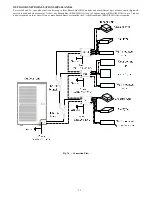
8. Tighten flare nut and finish installation using two wrenches
as shown in Fig. 72.
A07354
Fig. 72
-
Tighten Flare Nut