


22
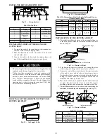
INSTALL THE ROUND AIR SUPPLY DUCT
1
2
4
3
5
6
7
8
9
Fig. 31
-
Air supply duct
Table 24—Air Duct
No.
Name
No.
Name
1
Return Air Duct
6
Transition Duct
2
Canvas Duct
7
Air Supply Duct
3
Return Air
Louver
8
Diffuser
4
Hanger
9
Diffuser Joint
5
Air Supply Duct
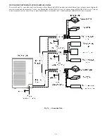
INSTALLATION STEPS OF THE ROUND AIR
SUPPLY DUCT
1. Pre- install the outlet of the round duct on the transition duct
and then secure it with the tapping screw.
2. Place the transition duct to the air outlet of the unit and
secure it with a rivet.
3. Connect the outlet to the duct and then tighten them with
tape. Other installation details are not covered herein.
S
The max. length of the duct means the max. length of the air
supply duct plus the max. length of the return air duct.
S
The duct is either rectangular or round and connected with
the air inlet/outlet of the indoor unit. Among all air supply
outlets, at least one should remain open. As for the round
duct, it needs a transition duct of which the size should
match with the air supply of the unit. After the fitting of the
transition duct, it is best to keep the round duct 32ft (10m)
away from the corresponding diffuser.
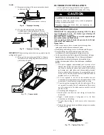
!
CAUTION
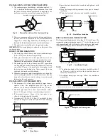
DRAWINGS OF THE AIR SUPPLY OUTLET AND
RETURN AIR INLET
21
A
B
Fig. 32
-
Air Supply Outlet
D
C
Fig. 33
-
Return Air Inlet
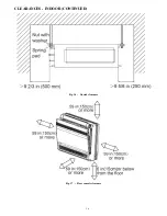
Table 25—Dimensions of the Air Supply Outlet and Return
Air Inlet (unit: in/mm)
Item
Air Supply Outlet
Return Air Inlet
Size
A
B
C
D
09
6 1/7 in
(156 mm)
26 in (662
mm)
22 5/6 in
(580 mm)
22 5/6 in
(580 mm)
12
18
6 1/7 in
(156 mm)
34 in (862
mm)
30 5/7 in
(780 mm)
6 3/8 in
(162 mm)
21
6 1/7 in
(156 mm)
41 4/5 in
(1062
mm)
38 4/7 in
(980 mm)
6 3/8 in
(162 mm)
24
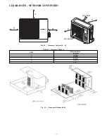
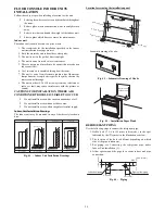
INSTALLATION OF THE RETURN AIR DUCT
1. The default installation location of the rectangular flange is
in the back and the return air cover plate in in the bottom as
shown in Fig.34.
Return Air Cover Plate
Downward Return Air
Backward Return Air
Rectangular Flange
Fig. 34
-
Return Air Duct
2. If the downward return air is desired, just change the place
of the rectangular flange and the return air cover plate.
3. Connect one end of the return air duct to the return air outlet
of the unit by rivets and the other to the return air louver.
For the sake of the convenience to freely adjust the height, a
cutting of canvas duct will be helpful, which can be
reinforced and folded by 8# iron wire.
4. More noise is likely to be produced in the downward return
air mode than the backward return air mode. We suggest
installing a muffler and a plenum box to minimize the noise.
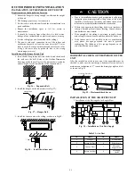
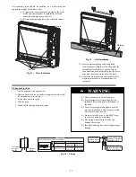
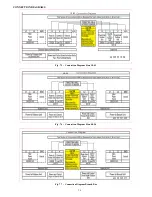
5. The installation method can be chosen with considering the
conditions of the building and maintenance etc. (see Fig. 35).
1
Wind supply
Back wind
Install the back wind pipe (a)
Wind supply
Install the back wind pipe(b)
Back wind
1
2
4
5
3
6
4
5
Fig. 35
-
Return Air Duct
Table 26—Air Duct
No.
Name
No.
Name
1
Return Air Louver
(with the filter screen)
4
Indoor Unit
2
Canvas Duct
5
Air Supply Duct
3
Return Air Duct
6
Access Grille