


24
FLOOR CONSOLE INDOOR UNITS
INSTALLATION
Follow these key steps when selecting a location for the unit.
S
Select a place where cool air can be distributed throughout
the room.
S
Select a place where condensation water is easily drained
away.
S
Select a site that can handle the weight of the indoor unit.
S
Select a place which has easy access for maintenance.
Indoor unit
The indoor unit should be sited in a place where:
1. The restrictions for the installation specified in the indoor
unit installation drawings are met.
2. Both the air intake and exhaust have clear paths.
3. The unit is not in the path of direct sunlight.
4. The unit is away from a heat or steam source.
5. There is no source of machine oil vapour (this may shorten
indoor unit life).
6. Cool (warm) air is circulated throughout the room.
7. The unit is away from electronic ignition type fluorescent
lamps (inverter or rapid stert type) as they may shorten the
remote controller range.
8. The unit is at least 3.28 ft (1 m) away from any television or
radio set (unit may cause interference with the picture or
sound).
CAUTIONS FOR INSTALLATION WHERE AIR
CONDITIONER TROUBLE IS LIABLE TO OCCUR
S
Do not install in areas with or near an abundance of oil.
S
Do not install in areas with an acid base area.
S
Do not install in areas with an irregular electrical supply.
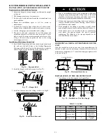
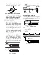
Indoor Unit Installation Drawings
The indoor unit may be mounted in any of the three styles shown
here.
Exposed
Floor lnstallation
Wall Installation
Molding
Mounting plate
Half conceated
Concealed
Grid(field supply)
Fig. 41
-
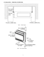
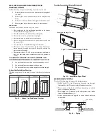
Indoor Unit Installation Drawings
Location for securing the installation panel
Schematic drawing of hooks:
7 7/8 in (200 mm)
27 5/9 in
(700 m
m)
25 1/3
in (644 mm
)
)
m
m
0
2
1(
ni
7/
5
4
)
m
m
0
2
2(
ni
3/
2
8
1 1/6 in (30 m
m)
6 2/7
in (16
0 mm
)
1 1/6 in (30 mm)
6 2/3 in (170
mm)
8 2/3 in (22
0 mm)
4 5/7
in (120 mm
)
22 4/9 i
n
(570 mm)
23 5/
8 in
(600
mm)
7 7/8 in (20
0 mm)
Fig. 42
-
Schematic Drawing of Hooks
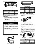
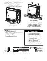
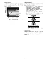
INSTALLATION
PAPER PLANK
Fig. 43
-
Installation Paper Plank
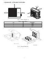
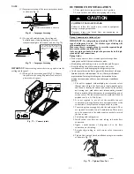
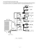
REFRIGERANT PIPING
Use the following steps to connect the refrigerant pipe.
1. Drill a hole (2 1/6 in (55 mm) in diameter ) in the spot
indicated by the
symbol in the illustration as below.
2. The location of the hole is different depending on which
side of the pipe is taken out.
3. For piping, see
Connecting the refrigerant pipe
, under
Indoor Unit Installation (1).
4. Allow space around the pipe for a easier indoor unit pipe
connection.
1 7/9 in (45 mm)
2 1/3 in (60 mm)
3 in (75 mm)
3 in (75 mm)
Wall
(Unit : in/mm)
Left bottom piping
Right bottom piping
Fig. 44
-
Piping