


35
INSTALL ALL POWER, INTERCONNECTING
WIRING, AND PIPING TO INDOOR UNIT.
1. Run interconnecting piping and wiring from outdoor unit to
each indoor unit (in matched pairs) (except sizes 48 and 56
refer to Branch Box installation instructions).
2. Pass interconnecting cable through hole in wall (outside to
inside).
3. Lift indoor unit into position and route piping and drain
through hole in wall (inside to outside). Fit the
interconnecting wiring into back side of indoor unit.
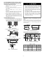
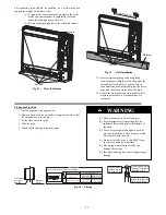
4. Hang indoor unit on upper hooks of wall mounting plate
(see Fig. 78).
A08283
Fig. 78
-
Hanging Indoor Unit
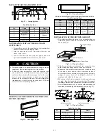
5. Open front cover of indoor unit and remove field wiring
terminal block cover (see Fig. 79)
Field Wiring
Cover
Interconnecting
Cable
A08279
Fig. 79
-
Field Wiring Cover
6. Pull interconnecting wire up from back of indoor unit and
position in close to the terminal block on indoor unit.
7. Push bottom of indoor unit onto mounting plate to
complete wall mount.
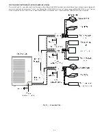
8. Connect wiring from outdoor unit per connection diagram
(see Fig. 75).
NOTE
:
Polarity of power wires must match original
connection on outdoor unit.
9. Replace field wiring cover and close front cover of indoor
unit.
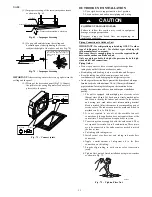
10. Connect refrigerant piping and drain line outside of indoor
unit. Refer to
Piping Connections to Outdoor Unit
section
and Fig. 72 for proper installation of flare connections.
Complete pipe insulation at flare connection then fasten
piping and wiring to the wall as required. Completely seal
the hole in the wall.
11. Repeat steps 1 through 10 for each indoor unit.
SYSTEM VACUUM AND CHARGE
UNIT DAMAGE HAZARD
Failure to follow this caution may result in equipment
damage or improper operation.
Never use the system compressor as a vacuum pump.
CAUTION
!
Refrigerant tubes and indoor coil should be evacuated using the
recommended deep vacuum method of 500 microns. The alternate
triple evacuation method may be used if the procedure outlined
below is followed. Always break a vacuum with dry nitrogen.
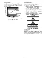
Using Vacuum Pump
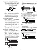
1. Completely tighten flare nuts A, B, C, D, (for all fan coils).
Connect gage charge hose to one circuit or all circuits (if
using a multiple connection manifold) at the low side
service valve charge port(s) (see Fig. 80.).
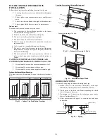
2. Connect charge hose to vacuum pump.
3. Fully open the low side of manifold gage (see Fig. 81).
4. Start vacuum pump.
5. Evacuate using either deep vacuum or triple evacuation
method.
6. After evacuation is complete, fully close the low side of
manifold gage and stop operation of vacuum pump.
7. If multiple connection manifold is not used, repeat the
procedure (1 through 6) until all indoor units and piping are
completely vacuumed.
8. The factory charge contained in the outdoor unit is suitable
for max pipe length. If an additional charge is required, it
should be added to the system as liquid at this time.
9. Disconnect charge hose from charge connection of the low
side service valve.
10. Fully open all service valves.
11. Securely tighten caps of service valves.
Outdoor Unit
Indoor Unit
Refrigerant
Service Valve
Low Side
High Side
A
B
C
D
A07360
Fig. 80
-
Service Valve
Manifold Gage
500 microns
Low side valve
High side valve
Charge hose
Charge hose
Vacuum pump
Low side valve
A07361
Fig. 81
-
Manifold