


30
INSTRUCTION
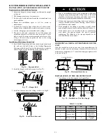
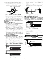
The slant gradient of the attached drain hose should be within 3 in.
(75 mm) so that the drain hole does not have to endure unnecessary
outside force.
3
in
(
75
mm)
19
2
/3 (
50
0 m
m
)
Fig. 64
-
Slant gradient
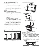
1. Install the drain hose according to the following process if
several drain hoses join together.
Fig. 65
-
Slant gradient
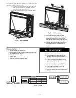
2. Check the smoothness of the drain after the installation.
3. Check the drain state by immitting 36 3/5 in3 (600 cc)
water slowly from the outlet vent or test hole.
4. Check the drain in the state of refrigerating after installing
the electric circuit.
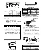
4 in (100 mm)
Fig. 66
-
Drain
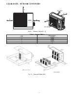
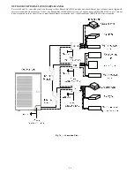
Electrical wiring
NOTE
: The power of the entire indoor unit must be connected in
the outdoor unit.
S
About the electrical wiring, see the circuit diagram attached
with the unit.
S
All electrical wiring installation must be done by
professional personnel.
S
Remove the earthing treatment.
Wiring method of connection unit and controller
Connection wiring (communication)
1. Open
the
electric
box
cover, drag
the wiring
(communication) from rubber plug A, and impact them well
individually with an impact fastener.
2. Wire according to the indoor side circuit diagram.
(1.) Fix the impact fastener after the connection.
(2.) Entwine the small sponge on the electric wire
(entwine to prevent condensation).
(3.) Impact tightly with an impact fastener after
connection. Then fir on the electric box.
(4.) Connect the 3 cord rubber wire to the counter
terminal of the 3 way terminal board.
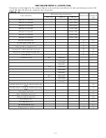
The power cord reference power cord standard recommending
table.
Fig. 67
-
Power cord
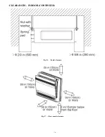
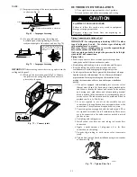
Install the panel
1. Set the panel to the indoor unit body by matching the posi-
tion of the panel’s swing flap motor to the panel’s piping
position to the indoor unit’s piping position (see Fig. 68).
2. Install the panel
(1.) Install the panel on the indoor unit temporarily.
When installing, hang the latch on the hook that is
located on the opposite side of the swing flap on
the panel of the indoor unit (two positions).
(2.) Hang the remaining 2 latches to the hooks on the
sides of the indoor unit. (Be careful not to let the
swing motor lead wire get caught in the sealing
material.)
(3.) Screw the 4 hexagon head screws under the latches
in about 3/5 in (15 mm). (The panel should rise)
(4.) Adjust the panel by turning it toward the direction
pointed by the arrow (see Fig. 68) so the adjust
board connects well to the ceiling.
(5.) Tighten the screws until the thickness of the sealing
material between the panel and the indoor unit is
reduced to 5- 8mm.
1/5 in to 1/3 in (5 mm to 8 mm)
Fig. 68
-
Panel Installation