background image

Intermec ColorCoder V4 – Service Manual Ed. 1

171

Chapter 4     Installation

4.2:F Relocation and

Transportation, cont'd.

Transportation by Land, Air, and Sea for Middle and Long Distances, cont'd.

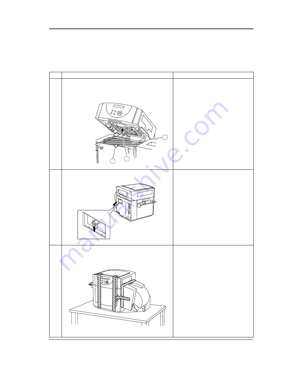
Procedure

1. Open the PHS unit. Lay two or three sheets of lint free wiper (1)

on the feed unit platen and secure them with filament tape (2).

2. Attach the recovery unit packing (3) to the recovery unit.

Open the sub cover in the rear side of the printer, push up the
opening/closing arm (green coloured lever) to  “TRANSPORTA-
TION MODE”.

1. Close the PHS unit.
2. Secure the front side (3 positions), rear sub-cover (1 position) and

roll cover rear (1 position) with filament tape.

No.

10

11

12

Inspection/Remarks

1

3

2

4.2 Unpacking and Installation, cont'd.

Summary of Contents for ColorCoder V4

Page 1: ...ColorCoderV4 ColorLabelPrinter P N 1 960470 00 Edition 1 August1999 Service Manual ...

Page 2: ... Output to Engine 1 PCB 2 2 22 F Input from and Output to Engine 2 PCB 23 G Input from and Output to Roll Holder PCB 24 H Input from and Output to DC Power Supply Unit 25 I Basic Sequence 26 J Motor Control 28 2 2 Image Formation System 32 A Outline 32 B BubbleJet Line Head 35 C Recovery Unit 37 2 3 Ink Supply System 47 A Outline 47 B Pump Unit 52 C Ink Cartridge 58 2 4 Pick Up Feeder System 59 A ...

Page 3: ... 151 B Installation roll type 152 C Installation fan fold type 160 D Check of Image and Operation 166 E Head Shading 167 F Relocation and Transportation 168 4 3 Daily Care by Customer 172 A Image Maintaining Functions 173 B Cleaning 174 5 Maintenance and Servicing 5 1 Parts to be Replaced Periodically 175 5 2 Consumable Parts 175 5 3 Maintenance 176 6 Troubleshooting 6 1 Preface 179 A Initial Insp...

Page 4: ...oration Swiss 721 is licensed from Bitstream Inc Swiss is a trademark of Bitstream Inc Courier Script are licensed from Canon Inc 6 Troubleshooting cont d 6 6 Diagnosis 229 A Malfunction Indications 229 B Warning Indications 233 6 7 Image Troubleshooting 236 A Measures to Take Against Faulty Images 236 6 8 Function Troubleshooting 242 A Measures to Take Against Malfunctions 242 6 9 Layout Function...

Page 5: ...d to correct the interference DOC Notice Canada Canadian Dept of Communication REGULATIONS COMPLIANCE DOC A This digital apparatus does not exceed the class A limits for radio noise emissions from a digital apparatus as set out in the radio interference regulations of the Canadian Department of Communication Ministère des Communications du Canada CONFORMITE DE REGLEMENTS DOC A Le présent appareil ...

Page 6: ... A2 1997 Class B EN 61000 3 2 1995 EN 61000 3 3 1995 EN 50082 1 1997 EN 50204 1995 EN 61000 4 4 1995 EN 61000 4 5 1995 EN 61000 4 6 1996 EN 61000 4 8 1993 EN 61000 4 11 1994 Electrical Safety EN 60950 1992 A1 A2 A3 following the provisions of Directives 89 336 EEC and 73 23 EEC Mölndal 1999 05 03 Mats Gunnarsson President 1 Intermec assumes no responsibility as regards fulfilling the CE Directive ...

Page 7: ...urpose tools Informationinthismanualissubjecttochange Notificationofsuch changes will be given in Printer Technical Bulletins The information contained in this Service Manual and the Printer Technical Bulletins is essential to proper maintenance of the ColorCoder V4 printer This Service Manual is supplemented by the following publica tions which the service technician also should keep easily avail...

Page 8: ...tdownloadfrom a host computer 4 It has a bar code printing function and is able to handle eight types of bar codes 5 Is has a partial rewrite overlay function which enables it to change part of the data with no need to stop printing 6 Ink recycle system newly installed taking waste ink generated through BJ head cleaning operation and put it back into ink supply system to reuse it for printing It s...

Page 9: ...label or fan fold Roll outside diameter Max 180 mm 7 08 Roll core diameter Paper tube 76 2 mm 3 Types Labels with backing paper and gap between labels Labels tickets with black mark Labels Tickets with hole Tags No TOF not supported by printer drivers Bar code types JAN UPC EAN series Codabar NW 7 Industrial 2 of 5 Inter leaved 2 of 5 MSI Code 39 Code 93 Code 128 Customer bar code edition function...

Page 10: ...n labels 2 Maintenance cleaning test printing adjusting position setting parameters setting interface 3 NVRAM save Detecting functions Checkspaper nopaper paperjam checksinkcartridges checks ink serviceman call door open no paper fed Head cleaning function Operates automatically and manually Ink consumption 17 000 sheets cartridge Conditions 12 5 Duty colour paper size 4 3 Memory card Can use card...

Page 11: ...eral Description 1 3PartsoftheMachine 1 3 A Front View 1 3 B Rear View 1 Control panel 2 PHS Printer Head Station unit 3 Roll cover 4 Power switch 5 Front cover 1 Sub cover 2 Power cord connector 3 Parallel interface connector 4 Manual cutter 1 2 3 4 5 1 2 3 4 ...

Page 12: ... panel 7 Roll retainer inner 2 Paper guide fixing screw 8 Roll retainer fixing screw 3 Paper guide inner 9 Roll retainer front 4 Paper guide front 10 Ink cartridges 5 Roll sensor lever 11 Memory card 6 Roll drive shaft 12 Front cover 1 Display 8 ENTER key 2 ON LINE key 9 Right cursor key 3 PAUSE key 10 READY lamp 4 STOP key 11 ON LINE lamp 5 FEED key 12 DATA lamp 6 MENU key 13 ERROR lamp 7 Left cu...

Page 13: ... View 1 BJ head 2 Recovery unit 3 Roll sensor lever 4 Roll drive shaft 5 Follower roller 6 Pinch roller 7 TOF inlet sensor 1 8 TOF inlet sensor 2 9 Rowel units 10 Engine 2 PCB 11 Delivery roller 12 Drive roller 13 TOF outlet sensor 1 14 TOF outlet sensor 2 15 Engine 1 PCB 16 Formatter PCB 17 DC power supply unit 1 3PartsoftheMachine cont d ...

Page 14: ...START ON LINE START OFF LINE PAPER TYPE TYPE 1 A 102X076 TYPE 2 C 102X076 TYPE 3 A 102X203 TYPE 4 C 102X203 TYPE 5 A 102X127 CLEANING A CLEANING B INTERVAL 99999 CUT INTERVAL CUT INT 99999 TOP MARGIN SET BOT MARGIN SET LEFT MARGIN SET LEFT MARGIN 00 RIGHT MARGIN SET RIGHT MARGIN 00 MEM CARD PRINT MEM CARD FORMAT MEM CARD COPY NOZ CHK PATTERN H NOZZLE ADJ C NOZZLE ADJ M NOZZLE ADJ Y NOZZLE ADJ Y NO...

Page 15: ...DENMARK 2 KOREA LATIN AMERICA SPAIN 2 LEGAL I F SET PARALLEL TYPE 1 TYPE 2 TYPE 3 CODE PAGE 850 CODE PAGE 850 CODE PAGE 850 CODE PAGE 850 CODE PAGE 850 CODE PAGE 850 CODE PAGE 850 CODE PAGE 850 CODE PAGE 850 CODE PAGE 850 CODE PAGE 850 CODE PAGE 850 CODE PAGE 850 CODE PAGE 850 CODE PAGE 437 CODE PAGE 437 CODE PAGE 437 CODE PAGE 437 CODE PAGE 437 CODE PAGE 437 CODE PAGE 437 CODE PAGE 437 CODE PAGE ...

Page 16: ...OP OF FORM SEL A LABEL GAP B LABEL MARKER C TAG MARKER D TAG HOLE E TAG NO T OF PAPER WIDTH SET PAPER LENGTH SET MARK WIDTH SET PAPER WIDTH 102 PAPER LENGTH 076 LABEL GAP 03 MARK WIDTH 4 LABEL GAP SET TOP OF FORM SEL A LABEL GAP B LABEL MARKER C TAG MARKER D TAG HOLE E TAG NO T OF PAPER WIDTH SET PAPER LENGTH SET MARK WIDTH SET PAPER WIDTH 102 PAPER LENGTH 203 LABEL GAP 03 MARK WIDTH 4 LABEL GAP S...

Page 17: ...agrams cont d TYPE 5 A 102X127 CLEANING MODE MODE A MODE B NVRAM NVRAM RESET NVRAM SAVE NVRAM PAPER WIDTH SET TOP OF FORM SEL PAPER LENGTH SET LABEL GAP SET MARK WIDTH SET A LABEL GAP B LABEL MARKER C TAG MARKER D TAG HOLE E TAG NO T OF PAPER WIDTH 102 PAPER LENGTH 127 LABEL GAP 06 MARK WIDTH 4 ...

Page 18: ...the gap between the labels Printing operation will take placeaftertheimageprocessingunitsendsanequivalentofoneline oftheprintingdatatotheimageformationunitatthetimewhenthe printingpositionreachestheblackhead Transmissionandprinting of an equivalent of one line of the printing data are repeated in synchronization with the feed of the paper to perform black printing From now on each time when the la...

Page 19: ...k supply system Clock function Backup memory function Interfaces with the formatter PCB Engine 2 PCB All about the BJ heads and the PHS unit such as cleaning are controlled Controls the image data transmission of the heads Controls the head drive and temperature Controls the head motor Controls the cap motor Controls the fan motors Figure 2 2 is a block diagram showing the printer s major circuits...

Page 20: ... Outline of Electrical Circuit cont d Image processing unit Power control Circuit Micro computer with ROM Gate Array Gate Array Formatter PCB Micro computer CG ROM Roll holder PCB Memory card holder RAM Motor driver Engine 1 PCB ROM Feeder motor Pump motor Motor driver Engine 2 PCB BJ head Black Head motor Cap motor Parallel interface Control voltage circuit Q1 Q2 Q11 Q39 Q40 Q41 J109 Q301 Q302 PH...

Page 21: ...peration and Timing 2 1 Basic Operation cont d 2 1 C Input from and Output to Formatter PCB J601 Formatter PCB Control panel Memory card J109 External device Cutter unit Option Engine 1 PCB Roll holder PCB J32 J106 J102 J104 Parallel J103 J307 J105 Figure 2 3 ...

Page 22: ... rotates counterclockwise When H pump motor rotates clockwise HTOF IN HTOF OUT TTOF IN TTOF OUT PHS SLND1 PHS SLND2 DOOR 5V 5V 5V 5V 5V PS4 PS5 Pressure cam H P sensor Recovery pump H P sensor J14 3 2 1 J15 3 2 1 J305 B4 B5 B6 B7 B8 B9 When H recovery pump is at home position 5V 5V PS12 Latch solenoid position sensor J16 3 2 1 B10 B11 B12 When H open close latch is closed 5V Cam pressure release c...

Page 23: ...sured with connector J304 disconnected if ink is full in ink cartridge several tens several handreds kΩ When resistance between each terminal and GND is measured with connector J304 disconnected if ink is normal condition in ink cartridge infinity Ω When resistance between each terminal and GND is measured with connector J304 disconnected if a new ink cartridge is set infinity Ω Ink remaining quan...

Page 24: ... head K BJ head C BJ head M BJ head Y J308 J312 M4 M3 FM1 FM2 FM3 Engine 1 PCB J406 J412 J407 J407 J409 1 2 3 4 5 6 7 8 9 10 11 12 J411 1 2 J18 J19 J22 1 2 J23 3 2 1 J24 3 2 1 J25 3 2 1 J26 3 2 1 Cap position sensor 1 Cap position sensor 2 Head position sensor 1 Head position sensor 2 PHS open close detection switch When H fan motor is turned ON FAN When H fan motor is turned ON J27 J28 J29 J30 J4...

Page 25: ...hen roll guide plate is pressed to roll H When no slack in roll paper L OPIEND When paper 4 inches wide is set voltage is approx 4V When paper 2 inches wide is set voltage is approx 0V Roll motor ON at H 5V 5V Roll sensor Paper width sensing slide rheostat Roll motor J61 3 2 1 J602 1 2 3 PS10 M5 7 8 J66 1 2 J64 3 2 1 J603 3 2 1 J103 Formatter PCB J601 J62 3 2 1 5 4 6 PS11 VRU1 Roll paper end senso...

Page 26: ...ching Shut down is going J001 002 J002 J001 1 2 3 4 5 6 314 J405 PC SLP SW SNS VH CONT VM CONT J108 1 2 3 4 5 6 J306 Power supply Unit Formatter PCB Engine 1 PCB Engine 2 PCB While power is on H While power is on L From time when power SW is turned on to time when shutdown is completed H See figure below While power is on H While power is on H J107 J002 12V 12V PC SLP SW SNS VH CONT VM CONT GND ...

Page 27: ...d Latch solenoid Pressure cam HP sensor Recovery pump HP sensor Pump motor Cam pressure release clutch PHS holder lock Pump unit initialization PHS unit initialization Motor Forward rotation Solenoid Lock Motor Backward rotation Solenoid Release Sequence PHS holder lock Pump unit initialization Supply solenoid open Pump pressure release Recovery pump HP Head position sensor 2 Head position sensor ...

Page 28: ... HDPRT BJ head printing operation PD Delivery operation after printing MVCP BJ head recovery system cap position movement SWBK Paper back feed operation Sequence Feeder motor TOF inlet sensor TOF outlet sensor Roll sensor Roll motor BJ head INIT HDCL MVPR HDPRT PD MVCP STBY SWBK HDCL MVPR HDPRT Initialization processing POWER ON START First printing START Second printing Motor forward rotation Mot...

Page 29: ... as follows Controls the motor ON and OFF Controls the direction of motor rotation Controls the speed of motor rotation ThreefanmotorsarestartedandstoppedbyQ401viathetransistor Q421 Startandstop androtatingdirectionoftherollmotorintherollunit is controlled by the gate array Q32 in the formatter PCB and the motor driver in the roll PCB Thefeedamountofthepaperisdetectedbytherollsensorwhilethe roll m...

Page 30: ...sic Operation cont d 2 1 J Motor Control cont d Figure 2 11 Engine 1 PCB 24V 12V Q348 Q313 Q317 M1 Feeder motor J301 1 2 3 4 5 FEEDMA FEEDMB FEEDMC FEEDMD FEEDME Q318 Q338 24V PUMPMA PUMPMB J302 13 14 Pump motor M2 Driver IC Gate array Driver IC Motor driver Control Circuit Driver IC ...

Page 31: ...ntrol cont d Figure 2 12 Motor driver Gate array Engine 2 PCB Q401 Q404 J407 8 6 4 9 7 5 M4 24V Cap motor CAPMA CAPMCOMA CAPMA CAPMB CAPMCOMB CAPMB Motor driver Q402 J407 14 12 10 15 13 11 M3 24V Head motor HDMA HDMCOMA HDMA HDMB HDMCOMB HDMB J408 2 1 4 3 6 5 FM1 FM2 FM3 Fan motor 1 Fan motor 2 Fan motor 3 24V Q421 FAN ...

Page 32: ...n cont d 2 1 J Motor Control cont d Figure 2 13 motor driver Gate array I O controller M5 5V 24V 5V Formatter PCB Roll holder PCB Roll sensor output detection circuit Roll motor J602 7 8 Q1 Q18 Q32 OPIMT1 OPIE B J601 6 5 2 J103 A8 A9 J602 3 2 1 Roll sensor 5V J602 6 5 4 Roll paper end sensor A12 ...

Page 33: ...ads to eject ink to form images on paper based on the printing data read from the memory card or the host computer The system consists primarily of a head holder unit and a recovery unit See Figure 2 14 for the basic construction of the image formation system Head motor Cap motor BJ head Recovery unit Restoration tub unit Absorber Tube connector Tube station Figure 2 14 ...

Page 34: ...lthe head ejection face reaches the printing position printingposition Figure 2 16 Printing position After printing operation completes the head is returned to the capping position by the opposite operation to the above The head holder unit is driven by the head motor M3 and the capping position and the printing position are controlled by the number of pulses driving the motor signal from the refe...

Page 35: ...processing unit to execute printing of an equivalent of one line The above mentioned operation is repeated in synchronization with the feed of the paper to form images Likewise for cyan magenta and yellow when the printing position of the paper reaches the respective BJ heads the printing operation is repeated to form colour images on the paper Basic Operation Sequence of Image Formation System Th...

Page 36: ...83mm 1344 nozzles Block 1 Block 2 Block 3 Block 4 Block 5 Block 6 Block 7 Block 8 Block 9 Block 10Block 11 1 2 3 1 1 1 6 7 8 2 2 2 Construction TheBJheadoftheprinterisprovidedwith11heaterchipsinwhich 128piecesofsmallheaterarearrangedinalengthofapproximately 9mm eachheaterhavinganejectionnozzleonit Theseheatersare driven by the driving signal from the engine 2 PCB to eject the ink out of the nozzle...

Page 37: ...y to have the bubbles grow 4 Expansion of bubbles When the bubbles grow to the maximum the ink is ejected out of the ejection face 5 Contraction of bubbles Thebubblesarecooleddownwiththeinktocontract Theinkatthe tip of the nozzle rushes out at the speed at which it is ejected 6 Destruction of bubbles The ink comes in contact with the heater surface to be abruptly cooled down 7 Supply of ink The in...

Page 38: ...ting the surplus ink adhered to the head nozzle surface The recovery unit takes the following conditions depending on the state and the purpose of the unit 1 Capping state 2 Head cleaning operation 3 Printing state Each operation will be described below Outline of Operation 1 Capping State Whilethepowersupplyisoffortheprinterisstandbystate thehead ismovedtothecappingposition andcoveredbytherestora...

Page 39: ...ry discharge position and the ink is ejected on the absorber in the restoration tub Figure 2 21 Pressurization Whentheheadisinthecappingposition closingthesuctionpump and the pressure pump feeds a trace of ink to the head to forcibly exhaust the in and bubbles inside the head nozzle See III INK SUPPLY SYSTEM 1 Outline of Operation C Operation of the Pressure Mode Circulation Whentheheadisinthecapp...

Page 40: ...s removed with a cleaner blade Figure 2 22 3 Printing Operation The restoration tub evacuates to the printing position the head nozzle face moves downward to about 2 9 mm above the platen about 1 5 mm from the paper and then printing operation starts Figure 2 23 2 2 Image Formation System cont d 2 2 C Recovery Unit cont d Head nozzle face Cleaner blade Restration tub BJ head Restration tub Platen ...

Page 41: ...otor However the evacuated position is detected by the head position sensor 2 Evacuation position to which the head evacuates when the restoration tub is moved Wipe position Position of head wipe operation Preliminary discharge position Position of preliminary discharge Capping position Position of capping and pressurizing Printing position Position of printing Operation of Restoration Tub Unit Th...

Page 42: ...ition sensor 2 PS9 Head position sensor 1 PS8 Head motor M3 BJ head Sequence MVPF PF MVCP 86 pulse 59 pulse MVPF PF MVCP Preliminary discharge position movement Preliminary discharge Cap position movement Figure 2 24 Figure 2 25 Head position sensor 2 PS9 Head position sensor 1 PS8 Head motor M3 Cap position sensor 1 PS6 Cap position sensor 2 PS7 Cap motor M4 Sequence MVWP WP MVCP 86 pulse 21 puls...

Page 43: ...tion mode Cleaning 1 Preliminary discharge Service mode Cleaning 2 Pressurizing head wiping preliminary discharge Auto cleaning After the head wiping waste ink is sucked Service mode Cleaning 3 Suction of waste ink started Pressurizing head wiping preliminary discharge Cleaning 4 Suction of waste ink started Ink circulation head wiping preliminary discharge Cleaning 2 x 4 Suction of waste ink pres...

Page 44: ...ting process is started Whentheintervalbetweentherecovery beforeprintingand start of printing is less than 30 minutes Recovery before printing before the printing process is started Cleaning when printing is interrupted Whentheprintingprocessisinterrupted thecleaningprocesstakes place as follows When the PHS lock is released CHK PAPER MID is indicated When the interval between the cleaning 3 and r...

Page 45: ...sity 12 5 When mode A is selected in the Cleaning setup menu 1 minute When mode B is selected in the Cleaning setup menu 3 minutes Cleaning during printing process 2 Afterthepreviouscleaning4 whenprintingonpaperequivalentto 2 500 sheets of standard paper 4 3 with standard image printing density 12 5 is completed cleaning 4 takes place However if paper has exhausted during the printing process and ...

Page 46: ... Recovery pump position sensor PS5 Pump motor M2 Cam pressure release clutch CL1 Pressure clutch CL2 Head position sensor PS9 Head position sensor PS8 0 4sec 20pulse 21pulse Cam press urized Cam pressure released Preliminary discharge position movement Cap position movement Ink pressurized Wait Preliminary discharge Waste ink suction wiping Wiping position movement Cap position movement 8 5sec 6 0...

Page 47: ...ressure clutch CL2 Suction clutch CL3 30sec 7 0sec 7 0sec 0 6sec 7 0sec 15sec 0 6sec Waste ink suction Cam pressure Preliminary discharge Wiping Wait Waste ink suction started ink circulation Waste ink suction completed Cam pressure release 40sec Pressurizing suction Post pressurizing Figure 2 29 Basic operation sequence of cleaning 4 Sequence Pressure cam position sensor PS4 Recovery pump positio...

Page 48: ...ink inside the BJ head and collection of the waste ink accumulated in therestorationtub Thebasicconstructionoftheinksupplysystem is shown below BJ Head Restoration tub unit Tube station Filter unit Ink remaining quantity detection sensor Sub tank Needle block Cartridge detection contact Ink cartridge Ink room lower Pressure release cam Suction pump Recovery pump Pressure pump Open close lutch Brea...

Page 49: ...ion Whentheinksupplysensordetectsnoinkinthe sub tank the ink supply operation takes place In the ink supply mode the open close latch of the sub tank is closed Under this condition the pressure pump executes the ink supplyoperationtosupplytheinktothesub tankfromthecartridge The inside pressure of the sub tank limits the amount of the ink to besuppliedtothesub tank Whentheinkexceedsacertainamount i...

Page 50: ...e pressure operation and the suction pump executes the suction operation The ink supply pressure of the pressure pump is slightlyhigherthanthereturnpressure inkcirculationpressure of the suction pump so that this pressure difference creates an inside pressure in the BJ head Therecoverypumpexecutesthesuctionoperationinordertoreturn the ink exhausted to the restoration tub into the sub tank Figure 2...

Page 51: ...pressure operation under this condition the ink is forcibly fed to the BJ head from the sub tank and exhausted out of the nozzle The recovery pump executes the suction operation to return the ink exhausted to the restoration tub into the sub tank Recovery pump home position sensor Recovery pump SL Outlet Release value Breather unit Inlet Latch solenoid Pull Latch lever Down Sub tank One way clutch...

Page 52: ...r the ink room CHECK CART takes place when no ink cartridge in the ink room Empty ink error Theamountoftheinkremainedischecked for the sub tank The error is detected at the time when the ink supply operation is completed Emptyinkerror takesplace when the ink remaining quantity detec tion sensor attached to the sub tank does sense no ink at the time when the ink supply operation is completed Ink ov...

Page 53: ...pressure release clutch Suction pump Pressure pump Pressure release cam Pressure cam home position sensor Pump retainers Pressure pump Thepressurepumpisdrivenbyengagingthepressureclutchwhile thepumpretainerpressesthetubingofthepump Byswitchingthe rotatingdirectionofthepumpmotor inkissuppliedeitherfromthe cartridge to the sub tank or from the sub tank to the BJ head Suction pump Thesuctionpumpisdri...

Page 54: ...ise direction by engag ingthecampressurereleaseclutch toplacethepressure release cam in the press position 2 The pump motor is driven in the clockwise direction by engag ing the pressure clutch CW CCW Suction clutch Pressure clutch Pump motor Recovery pump Recovery pump home position sensor Cam pressure release clutch Suction pump Pressure pump Pressure release cam Pressure cam home position senso...

Page 55: ...e cam in the pressure position 2 The pump motor is driven in the counterclockwise direction by engaging the pressure clutch and the suction clutch 2 3 Ink Supply System cont d 2 3 B Pump Unit cont d Figure 2 38 CCW CW CW Suction clutch Pressure clutch Pump motor Recovery pump Recovery pump home position sensor Cam pressure release clutch Suction pump Pressure pump Pressure release cam Pressure cam...

Page 56: ...essure release cam in the pressure position 2 The pump motor is driven in the counterclockwise direction by engaging the pressure clutch 2 3 Ink Supply System cont d 2 3 B Pump Unit cont d Figure 2 39 CCW CW Suction clutch Pressure clutch Pump motor Recovery pump Recovery pump home position sensor Cam pressure release clutch Suction pump Pressure pump Pressure release cam Pressure cam home positio...

Page 57: ...ch toplacethepressurereleasecaminthereleaseposition All the pumps without the recovery pump are stationary 2 3 Ink Supply System cont d 2 3 B Pump Unit cont d Figure 2 40 Suction clutch Pressure clutch Pump motor Recovery pump Recovery pump home position sensor Cam pressure release clutch Suction pump Pressure pump Pressure release cam Pressure cam home position sensor Pump retainers ...

Page 58: ...appearedthroughtheheadcleaningandputtingitbackto the ink supply system to re use Fine grains and foreign matters containedinthewasteinkneedtoberemovedinordertore usethe waste ink The waste ink collected through the recovery pump is designedtorunthroughthefilterunitbeforerunningbacktothesub tank thus the fine grains and foreign matters are filtered and the waste ink is reinstated for re use for pri...

Page 59: ...part Ink tank Stores ink to be used for printing Cartridge detection contacts Contactsforbeingdetectedthepres ence or absence of the cartridge by printer Slots to prevent misinsert Slotstoensurethattheinkcartridge is inserted into the fixed position for each colour The cartridge can notbeinsertedintowrongposition Figure 2 41 Cartridge detection contact Slots to prevent misinsert Ink tank Ink suppl...

Page 60: ...ept In case of the fan fold paper the paper can be supplied by removing the roll unit drive system and setting the dip switch on the roll holder PCB The paper supplied is fed on the feeder belt of the feeder unit The feeder belt is driven by the rotations of the feeder motor in the feeder unit The start position of printing is sensed by the TOF inlet sensor 1 or 2 and poor feeding of the paper is ...

Page 61: ...der motor drives the feeder belt The paper to be fed is controlledbythemotordrivesignalissuedfromtheengine1PCB The normal feed speed is 150 mm sec however the speed will decrease for the following cases 1 Whiletheheadtemperatureisincreasing theprintingoperation is executed at a speed of 50 mm sec 2 Thepartialrewritingincludingvariabledataspendsometimein developing data A printing speed is selectab...

Page 62: ...ne Pick up operation of this machine indicates the procedure that requiredquantityofpaperissuppliedtothefeederunitfromtheroll paper and fan fold paper Figure 2 43 Figure 2 44 Slide rheostat unit Roll paper end sensor Roll sensor lever Roll sensor Roll drive shaft Roll paper Roll holder PCB Slide rheostat unit Roll holder PCB Fan fold paper ...

Page 63: ...sensor lever and the roll drive shaft stops rotating Figure 2 45 Whenprintingisstartedandpaperisfed theslacknessiseliminated and the paper pushes the roll sensor lever Then the roll sensor is unblocked and the roll sensor ON signal is sent to the roll holder PCB The roll holder PCB detects the roll sensor ON signal issues a roll motor drive signal rotates the roll drive shaft and sends the paper W...

Page 64: ...ltage signal is transmitted to the engine 1 PCB throughtherollholderPCBandformatterPCBandA Dconverted The paper guide front setting position is detected based on the converted value to recognize the width of the paper Figure 2 47 Slide rheostat unit Paper guide Feedback operation When a printing operation is completed and the next printing process is started or when the printing process is interru...

Page 65: ... delivered out of the outlet When printing is started resumed next the feed belt and roll unit roll drive shaft is reversed only when roll paper is used to return the top of the paper next to the printed paper to the position of the TOF inlet sensor 1 or 2 Figure 2 49 Roll drive shaft When the top of the next paper returns to the position of the TOF inlet sensor 1 or 2 paper pick up and feeding op...

Page 66: ...ll sensor lever is fully pushed Then light to the roll paper end sensor is blocked and the roll paper end detection signal is sent to therollholderPCB WhentherollholderPCBdetectstherollpaper end detection signal it stops rotation of the roll drive shaft At the sametime therollpaperenddetectionsignalissenttotheformatter PCBthroughtherollholderPCBand NOPAPER isindicatedon the operation panel Roll dr...

Page 67: ...ed belt and the delivery roller These are driven by the feeder motor Five rowels provided along thefeederpathpreventthepaperfrombeingoff contact Thefeeder motorisofa5phasetype Duringtheprintingoperation every70 5 mm an equivalent of one line of 360 dpi paper fed an equivalent of one line of the ink of the BJ head is ejected Delivery rowel Rowels Feeder motor Pinch roller Roll paper Feed belt Roll ...

Page 68: ...nitialization processing POWER ON START First printing START Second printing Motor forward rotation Motor backward rotation Cleaning processing Head printing position movement Head cap position movement Cleaning processing Head printing position movement 1 Only when roll paper is used Sequence Operation INIT Head recovery system initialization operation HDCL Head cleaning processing MVPR Printing ...

Page 69: ...error WhenthepaperisnotfedtotheTOFsensorwithinaspecifiedtime after print starting 1 Paper feed error at the pick up assembly When the TOF mark of the paper does not reach the TOF inlet sensor within a specified time after print starting CHK PAPER MID When first sheet of paper is at the TOF inlet sensor NO PAPER FED When the first sheet of paper is not at the TOF inlet sensor 2 Paper feed error at ...

Page 70: ...pecified time 5 Paperfeederror AftertheTOFmarkisdetectedbytheTOFinlet sensor theTOFinletsensorcannotdetectnextTOFmarkwhile a specified time PRINT Normal condition Paper feed motor Inlet TOF sensor Outlet TOF sensor Approx 0 06 sec PRINT Abnormal condition ERROR Abnormal Approx 0 06 sec Approx 0 06 sec PRINT Normal condition Paper feed motor Inlet TOF sensor Approx 0 05 sec PRINT Abnormal condition...

Page 71: ...terface System 2 5 A Outline The control interface system which controls overall operation of the printer and interface system consists primarily of a formatter PCB Figure 2 54 Host computer Engine 2 PCB Engine 1 PCB Formatter PCB Control system Parallel interface Y M C K BJ head Memory card ...

Page 72: ...completed the formatterPCBwillsendaprintstartsignaltotheengineunit where the initialization of the head the paper feed operation and the counting operation of the print start position are executed Whenthepaperreachestheprintstartposition anequivalentofone blacklineoftheprintingdataaresentfromtheimagedataofthebit mapRAMinsidetheformatterPCBtotheblackheadviatheengine 1 and 2 PCBs At the head these d...

Page 73: ... data arestored the gate array in the formatter PCB starts to identify whether the printing data are the image data or the code data If the printing data are image data the data are transmittedtothebitmapRAMinsidetheformatterPCB andafter transmissionofthedatacompletes theprintingoperationwillstart Ontheotherhand theprintingdataarethecodedata thegatearray developstheimagedatainthebitmapRAMinaccorda...

Page 74: ...ta commands Figure 2 56 When the printing data are transmitted from the host computer via the parallel interface the signal is received by the CPU inside the formatter PCB If the printing data are image data the data are transmittedtothebitmapRAM andaftertransmissionofthedata completes the printing operation will start On the other hand the printing data are the code data the gate array develops t...

Page 75: ...nected to the formatter PCB and has the following functions LCD displays status errors of the printer LEDs displays operating conditions of the printer Eightswitchescontrolprintingconditionsoftheprinter suchas start stop and pause Figure 2 57 READY DATA ERROR MENU PAUSE ON LINE FEED STOP ENTER Ready lamp Data lamp Display panel Error lamp Menu key Right cursor key Enter key Left cursor key On line...

Page 76: ... signals of LEDs and inputting the output signals of the key switches CSLED IndicatesthatthesignalonthedatabuslinesistheON OFF signal of LEDs CSKEY Requeststheoutputsignalofthekeyswitchtothedata bus line LCDECK Indicates clock signals on which written in signal is about to be sent to LCD controler and read out signal is about to be sent from LCD controler WR Indicatesthatthesignalonthedatabuslinei...

Page 77: ...es andtheprinter will be the on line state immediately after the operation completes 3 If the feed key is pressed during this period the printer feeds one sheet of the paper If the feed key is pressed instantaneously during this term the printer feeds one sheet of the paper for about 10mm The key can be used even while an operation call error has occurred If the feed key and right cursor key are p...

Page 78: ...supply unit Formatter PCB Engine 1 PCB Engine 2 PCB BJ head Yellow 5V 24V BJ head Magenta 5V 24V BJ head Cyan 5V 24V BJ head Black 5V 24V 24V 12V 5V 5V 12V 24V 12V 24V 24V 24V 5V Sensor Motor ClutchSolenoid Battery BH301 AC 5V 24V 24V VM CONT VH CONT SW SNS SLEEP Counter PCB 5V Roll holder PCB 24V 12V 5V Control panel 5V 5V 5V 24V Motor Counter Sensor 24V 24V 24V 5V Sensor Motor Solenoid Fan motor...

Page 79: ...the control circuit in the DC power supply unit The following are the descrip tion on the operation 1 When the power switch is turned ON Turning the power switch on causes 5 VDC 12 VDC 12 VDC and 24VDC to each PCBs to be output by means of the function of the control circuit in the DC power supply unit 2 When the power supply is turned OFF By turning the power switch off the DC power supply unit o...

Page 80: ...a rule avoid operating the machine with any of its parts removed 5 Unless otherwise noted re assembly is the reverse of disassembly Figure 3 1 Figure 3 2 1 3 8 2 7 9 6 5 4 1 Control panel 2 2 PHS cover 2 3 Front cover 4 Left cover 2 5 Rear cover 3 6 Sub cover 7 Roll cover 8 Inner cover 2 9 Manual cutter tightened together with the 2 left cover Note The number in parentheses indicates the number of...

Page 81: ...1 A External Covers cont d Detaching the External Covers 1 Remove the two mounting screws 2 from the PHS cover 1 and detach the PHS cover Figure 3 3 SeeChapter3 1 BControlPanelastohowtodetachthecontrol panel 2 Removethetwomountingscrews 3 fromtheleftcover 1 and manual cutter 2 Figure 3 4 2 1 1 2 3 ...

Page 82: ... Covers cont d Detaching the External Covers cont d 3 Remove the three mounting screws 2 from the rear cover 1 and detach the rear cover Figure 3 5 4 Open the front cover 5 Remove the two mounting screws 2 from the inner cover 1 and then slide the inner cover in the left direction to detach Figure 3 6 1 2 2 1 ...

Page 83: ... 6 3 2 1 7 Precautions in disassembling and re assembling 1 AlwaysremovethecontrolpanelPCB with the housing face down because thekeytopsandtheconductiverubber sheet can come off together with the panel when re moving it 2 Before re assembling clean the conductive rubber sheet and the contacts of the pattern of the control panelPCBwithanairbrushtoremove chips and dust 3 Before re assembling clean t...

Page 84: ...rvice mode The control panel andotherelectricalcomponentsandconnectorsmustallbeconnectedsothat whenthepowerswitchisturnedon themachineisreadyfornormaloperation Note Always make sure efficiency of head shading when you have replaced the heads of C M Y or adjusted horizontal registration If it is necessary make a new data of the head shading See Chapter 6 4 Head Shading 1 Detach the PHS cover see Ch...

Page 85: ...headandtheconnectoroftheengine2PCB and detach the flexible cable Figure 3 10 4 Release the tube release lever 1 Figure 3 11 Caution Neveropenthetubereleaselever ifit snotnecessary Ifopened carryoutthe procedure for initial ink fill after re assembling in compliance with Chapter 3 3 B Punp Unit Precautions in assembling last page 3 2 Image Formation System cont d 3 2 A BJ Head cont d 1 ...

Page 86: ... tube station and close the tube release lever Caution 1 Removetheinkormarkclingtothetubestation jointswiththetubestation with the lint free sponge 1 901800 00 2 Connectorpacking 1 901808 00 mustbecleanedwiththelint freesponge 1 901800 00 before installed in order to prevent for foreign substance dust or ink from coming in the tubes 3 Move the BJ head with the tube connector being parallel and pla...

Page 87: ...ever breathe out on the BJ head especially the face and keep off from water oil and solvent 3 Never allow the BJ head to dry nor expose it to dust Put it back to the capping position as soon as possible when it is removed from the machine 4 If the situation requires cleaning of the BJ head always use the newlint freesponge 1 901800 00 andclearink 1 901805 00 Wipe off the face at a stroke slightly ...

Page 88: ...leaveaprotectivetapeon theheadfaceduringthework andpeelitoffjustbeforetoassemblingthehead to the printer 1 Install the heat sink 3 to the head main body 1 with the four screws 2 Fasten the screws in the order of A temporary tightening B C D A Figure 3 15 2 Affix the absorbtion sheet 2 to the back side of the connector cap 1 Figure 3 16 3 Select the tube connector matching with the colour of the BJ...

Page 89: ... Figure 3 17 4 Puttheconnectorcap 3 onthetubeconnector 1 andconnect the tube connector 1 to the head connector 2 of the BJ head Ensure that the rubber packing 4 is fixed in the correct direction Figure 3 18 Caution 1 Since the foreign substance in the BJ head connector causes ink leakage clean it with the lint free sponge 1 901800 00 before connecting 2 Whentherubberpackingcomesofffromtheconnector...

Page 90: ...nts and connectors must all be connected so that when the power switch is turned on the machine is ready for normal operation 1 OpenthePHSunit 1 Placesomelint freetowels 2 onthefeed unit bring its rear side to the TOF inlet and outlet sensors 1 Figure 3 19 2 Close the PHS unit 3 Peel off the protective tape on the head face Temporarily place theBJhead 1 ontheheadholderunitbyputtingonitalongthe gui...

Page 91: ...he BJ head in and be sure to connect the connector 1 positively Figure 3 21 5 Connect the power cord to a wall outlet and turn the power on in service mode see Chapter 6 5 Service Mode 6 Movetheheadtotheprintingpositioninthemaintenancemode Head Print Cap menu 7 Push into the temporarily placed BJ head and bring the both sidesoftheBJhead 1 tothebottomface 2 oftheheadholder Figure 3 22 3 2 Image For...

Page 92: ...thePHSunit Removetheheadmountsheetplacedonthe feed unit 11 Close the PHS unit 12 Release the tube release lever and remove the transportation connectors 1 901806 00 from the tube stations 13 Remove the connector packing 1 901808 00 from the tube connectors 1 and connect the tube connectors to the tube stations Figure 3 24 14 Close the tube release lever Attach the PHS cover 15 Execute SETUP CLEANI...

Page 93: ...ing the BJ head cont d 17 Execute Cleaning B 18 Execute Cleaning A 19 Check the image quality with NOZ ADJ PAT TERN and NOZ CHK PATTERN Execute adjustment of the registra tion if necessary see Chapter 6 3 Test Print Test Pattern 3 2 Image Formation System cont d 3 2 A BJ Head cont d ...

Page 94: ...ternals 2 DetachtheBJhead seeChapter3 2 A DetachingtheBJhead 3 Open the PHS unit 4 Remove the two mounting screws 2 from the operation panel support plate 1 and detach the plate Figure 3 25 5 Removethethreescrews 2 fromthePHSrightundercover 1 and detach the cover Remove the mounting screw 4 and disconnect the connector 5 from the right fan unit 3 and detach the fan unit Figure 3 26 2 2 1 2 4 3 5 2...

Page 95: ...ionsensors1and2 1 Remove the mounting screw 2 and toothed washer from the grounding wire and remove the grounding wire Figure 3 28 8 Detach the recovery tubing 1 from the recovery pump Figure 3 29 3 2 Image Formation System cont d 3 2 B Recovery Unit cont d Marking 2 1 Do not remove the painted screw 1 2 1 Caution When the recovery tubing is removed suck the waste ink in the tubing with the paper ...

Page 96: ...ly adjusted in mounting position of BJ heads and recoverysystembeforeshipment follow the precaution below 1 The whole recovery unit is not replaceable as a unit except some of itscomponents Theheightoftheblade cannotbeajustedtotheejectionface If the height is not appropriated the ink may splash out or non fire When the blade needs to be replaced you should replace the hole unit of the PHS unit 2 D...

Page 97: ...ved beforehand 2 After installation of the recovery unit has been completed BJ head must be installed inaccordancewithChapter3 2 ABJHead InstallingtheBJhead to protect the head face 1 Install the restoration tub plate 1 to the restorationtub unit 2 and fit the claws 3 and 4 in it and then fix the unit with two screws 5 Figure 3 34 2 Runtherecoverytubes 2 oftherecoveryunit 1 totherearside through b...

Page 98: ... the connectors J21 J22 2 to the cap position sensors 1 2 1 and fix the grounding wire 3 with the screw Figure 3 36 4 Insert the claws 1 of the further side of therecovery unit in the holes 2 oftherecoverysupportplateandpushittothebottom Figure 3 37 3 2 Image Formation System cont d 3 2 B Recovery Unit cont d 2 3 1 2 1 ...

Page 99: ...ution in assembling Sincetherecoveryunitpositioningstopper 2 andtherecoverysupportplate 1 of Figure 3 37 are precisely adjusted in mounting position screws 6 Inserttherecoverytubeintotherecoverypumpcompletelyand connect with recovery pump 7 Installthepinchrollerunit 1 tothepositionmarked andfixwith the two screws 2 Figure 3 39 3 2 Image Formation System cont d 3 2 B Recovery Unit cont d 1 2 2 3 Ma...

Page 100: ...on System cont d 3 2 B Recovery Unit cont d Installing the Recover Unit cont d 8 Installtherightfanunit 1 andfixwithonescrew 2 Connect withtheconnector 3 Installthelower rightPHScover 4 with three screws 5 Figure 3 40 9 Install the BJ head see Chapter 3 2 A Installing the BJ head 4 1 3 5 2 5 ...

Page 101: ...hetransportationconnector forBypass1 901809 00 to the tube station and close the tube release lever 2 Caution 1 Before attaching the transportation connectors 1 901809 00 to the tube stations clean the transportation connectors with lint free sponge 1 901800 00 to prevent foreign material dust or contaminated ink from enteringtheconnectionareasofthetubestationsandtheinsideofthetubes 2 Be sure to a...

Page 102: ... Formation System cont d 3 2 C Fan Unit cont d Detaching the Fan Unit cont d 5 Remove the two mounting screws 2 from the tube station 1 and detach the tube station Figure 3 42 6 DisconnecttheconnectorsJ20andJ21 1 Detachthetie wraps 2 and then remove the wiring cable Figure 3 43 2 1 1 2 ...

Page 103: ...t d Detaching the Fan Unit cont d 7 Remove the five mounting screws 1 from the PHS rear plate 2 and detach the fan unit Figure 3 44 8 DisconnecttheconnectorsJ20andJ21 1 fromthebacksideof thefanmountingplate anddisengagetheclaw 3 ofthefanrear duct 2 and then detach the fan rear duct Figure 3 45 9 Detach the fan motor 1 1 2 1 3 2 ...

Page 104: ... Formation System cont d 3 2 C Fan Unit cont d Detaching the Right Fan Unit 1 Detach the external cover see Chapter 3 1 Externals 2 DisconnecttheconnectorJ22 1 disengagetheclaws 3 ofthe fan right holder 2 2 and then detach the fan right holder 2 Figure 3 46 3 Detach the fan motor 3 2 1 ...

Page 105: ...ver see Chapter 3 1 Externals 2 Detach the fan unit see 3 2 C Detaching the Fun Unit 3 Disconnect the connectors J18 and J19 1 Figure 3 47 4 Remove the three mounting screws 2 from the motor unit 1 and detach the motor unit Figure 3 48 Caution Install the motor unit properly so that the head holder the recovery unit and gear back lash of two motors work precisely 3 2 1 2 2 1 ...

Page 106: ... Mechanical System 3 2 Image Formation System cont d 3 2 D Motor Unit cont d Detaching the Motor 1 Removetheonemountingscrew 2 fromthegearcover 1 and detach the gear cover Figure 3 49 2 Pull out the gears 1 and 2 while expanding the claw Figure 3 50 2 1 1 2 ...

Page 107: ...al System Detaching the Motor cont d 3 Disengage the two E rings 1 and pull out the two gears 2 Figure 3 51 4 Remove the two mounting screws 2 from the cap motor 1 and detach the motor Figure 3 52 3 2 Image Formation System cont d 3 2 D Motor Unit cont d 2 2 1 1 2 1 ...

Page 108: ...Service Manual Ed 1 107 Chapter 3 Mechanical System Detaching the Motor cont d 5 Remove the two mounting screws 2 from headmotor 1 and remove the motor Figure 3 53 3 2 Image Formation System cont d 3 2 D Motor Unit cont d 2 1 ...

Page 109: ...ply System 3 3 A Upper Ink Room Detaching the Upper Ink Room 1 Detach the external cover see Chapter 3 1 Externals 2 Remove the two mounting screws 2 from the upper ink room 1 and pull out the upper ink room to the near side Figure 3 54 3 Disconnect the connector J78 1 Figure 3 55 2 1 1 ...

Page 110: ... release lever 3 Disconnectthefourtubeconnectors 1 andclosetheconnector cap 2 Figure 3 56 4 Install the shipping connector 1 901809 00 1 to the tube station and close the tube release lever 2 Figure 3 57 Caution Never open the tube release lever if it s not necessary If opened carry out the procedure for initial ink fill after re assembling in compliance with Chapter 3 3 B Pump Unit Precautions in...

Page 111: ...p Unit cont d Detaching the Pump Unit cont d 5 Remove the three tie wraps 1 of the lower ink room and disconnect the connectors J71 J76 J77 and J79A 2 Figure 3 58 6 Removethemountingscrew 2 andtoothedwasher 3 fromthe grounding wire of the rear crossmember 1 and remove the grounding wire 4 Figure 3 59 2 1 2 2 3 1 4 ...

Page 112: ...l System Detaching the Pump Unit cont d 7 Remove the two mounting screws 2 from the tube station 1 and detach the tube station Figure 3 60 8 Remove four recovery tubes 1 from the recovery pump Figure 3 61 2 1 3 3 Ink Supply System cont d 3 3 B Pump Unit cont d 2 1 3 2 ...

Page 113: ...t cont d 9 Removethefourmountingscrews 2 fromtherearcrossmember 1 and disconnect the wire clip 3 and wiring cable and then detach the rear crossmember Figure 3 62 10 Remove the two mounting screws 2 from thelower ink room 1 Figure 3 63 3 3 Ink Supply System cont d 3 3 B Pump Unit cont d 2 1 3 2 2 1 ...

Page 114: ...unit 1 and detach the lower ink room 3 by pulling it toward you Figure 3 64 Caution Donottiltthepumpunitmorethannecessary becausetheinkinthepumpunit may leak out of the unit 12 Remove the two mounting screws 2 from thelower ink room 1 and detach the pump unit from the lower ink room Figure 3 65 3 3 Ink Supply System cont d 3 3 B Pump Unit cont d 2 3 1 2 1 ...

Page 115: ... free towel Do not tilt the pump unit 2 When the pump unit is detached the ink may leak out of the unit Conduct work on a tray or on a sheet 3 Whenmovingortransportingthepumpunit detached suckouttheinkfrom the sub tank beforehand and pack is with a special packaging material 4 When sucking out the ink from the inside of the sub tank suck out from the joint 8 positions of the tube station using a s...

Page 116: ...ump Unit cont d Detaching the Parts and Units Detaching the filter unit 1 Unhook the spring 1 2 Removethethreemountingscrews 3 fromthepumpcover 2 removethetubing 4 fromtheclaw anddetachthepumpcover Figure 3 66 3 Detach the recovering tube 1 4 Remove the screw 2 detach the filter unit 3 Figure 3 67 3 2 1 4 2 3 1 ...

Page 117: ...olenoid 1 2 Remove the mounting screw 3 Detach the steel core rand detach the latch solenoid Figure 3 68 Detaching the breather unit 1 Remove the latch solenoid 2 Remove the spring 1 3 Disconnect the connector 2 4 Remove the breather joint 3 for 4 places 5 Remove two screws 4 and detach the breather unit Figure 3 69 3 3 Ink Supply System cont d 3 3 B Pump Unit cont d 4 2 1 3 2 1 3 4 ...

Page 118: ...cont d Detaching the Parts and Units cont d Detaching the Needle Block 1 Unhook the spring 1 2 Removethethreemountingscrews 3 fromthepumpcover 2 removethesuctiontube 4 fromtheclaw anddetachthepump cover Figure 3 70 3 Removetheeighttubes 3 whichareextendingfromtheneedle block 1 to the sub tanks 2 Figure 3 71 3 1 2 4 2 3 1 ...

Page 119: ...1 Figure 3 72 Warning The needle block of the pump unit is sharp in it s tips and is dangerous Care should be taken for handling And always put the needle cover on the tips of the needle block when detached When disposing of it careful action should becarriedouttomakesurethesafety suchas crushingthetipsandwrapping it with durable protection 3 3 Ink Supply System cont d 3 3 B Pump Unit cont d 2 1 ...

Page 120: ...nits cont d Detaching the recovering pump home position sensor 1 Disconnect the connector J15 2 unhook the claw and then detach the recovery pump home position sensor 1 Figure 3 73 Detaching the pressure cam home position sensor 1 Disconnect the connector J14 2 unhook the claw and then detach the pressure cam home position sensor 1 Figure 3 74 1 2 2 1 ...

Page 121: ...erytubes black 5 andcyan 6 throughbetween the suction tubes cyan 2 and magenta 3 Pass the recovery tubes magenta 7 and yellow 8 through between the suction tubes magenta 3 and yellow 4 3 Pass the four pressure tubes 9 10 11 and 12 through the right side viewed from the machine side of the four recovery tubes 5 6 7 and 8 Figure 3 75 4 When assembling the overflow tubing of the breather unit see fig...

Page 122: ...ease lever and remove the transportation connectors 1 901809 00 from the tube stations 4 Remove the connector packing 1 901808 00 from the tube connectors andconnectthetubeconnectorstothetubestations 5 Close the tube release lever Attach the PHS cover 6 Execute Cleaning B 7 Exit from the service mode and enter in the normal mode see Chapter 6 5 Service Mode 8 Execute Cleaning B 9 Execute Cleaning ...

Page 123: ...3 4 A Roll Unit 3 4 Pick Up Feeder System Removing the Roll Unit 1 Remove the external cover 2 Remove the two screws 2 fixing the roll right cover 1 and remove the cover Figure 3 76 3 Remove the three screws 2 from the roll rear cover 1 and remove the cover Figure 3 77 1 2 1 2 ...

Page 124: ...System 3 4 A Roll Unit cont d 3 4 Pick Up Feeder System cont d Removing the Roll Unit cont d 4 Disconnect the connector J65 2 of the roll harness 1 Figure 3 78 5 Remove the three screws 2 from the roll unit and remove the roll unit 1 from the printer Figure 3 79 1 2 1 2 ...

Page 125: ... 1 Untighten the screw 1 fixing the roll retainer and remove the roll retainer front 2 from the roll drive shaft 3 2 Untighten the screw 5 fixing the roll retainer inner 4 and remove the roll retainer from the roll drive shaft 3 Remove the spacer 6 from the roll drive shaft Figure 3 80 4 Remove four screws 2 fixing the roll motor cover 1 and remove the cover Figure 3 81 3 1 2 4 5 6 1 2 2 ...

Page 126: ...Unit cont d Removing the Roll Drive Shaft cont d 5 Pull out the roll drive shaft 1 Figure 3 82 Caution for installation of roll drive shaft When installing the roll drive shaft 1 push the drive gear 2 against the motorbracket 3 inarrowmarkdirection toeliminateplayinthedriveshaft and then fix the roll drive shaft holding the roll retainer inner 4 1 4 1 3 2 ...

Page 127: ...er System cont d Removing the Roll Drive Unit cont d Removing the Roll Motor 1 Remove the connector J63 2 of the roll motor 1 Figure 3 83 2 Remove the grip ring 2 from the roll motor drive gear 1 and detach the gear 3 Remove three mounting screws 4 from the roll motor 5 and detach the motor Figure 3 84 1 2 1 3 4 2 ...

Page 128: ...ng screw 2 from the lever fixing arm 1 and detach the roll sensor lever 3 Figure 3 85 Removing the paper guide front 1 Remove the mounting screw 2 from the roll lower cover 1 and detach the cover 2 Remove the mounting screw 3 from the paper guide Figure 3 86 3 4 A Roll Unit cont d 3 4 Pick Up Feeder System cont d 3 2 1 2 1 3 ...

Page 129: ...emove the spring 3 and detach the paper guide front 4 Figure 3 87 Removing the roll sensor and roll paper end sensor 1 DisconnecttheconnectorJ61 2 fromtherollsensor 2 andthe connector J62 4 from the roll paper end sensor 3 2 Remove the three mounting screws 6 from the roll sensor mount 5 and detach the roll sensor and roll paper end sensor from the mount removing the claws of the sensors Figure 3 ...

Page 130: ...slide rheostat unit 1 DisconnecttheconnectorJ64 2 fromthepaperwidthdetection slide rheostat unit 1 Figure 3 89 2 Removethemountingscrew 2 fromthepaperwidthdetection sliderheostatunit 1 anddetachthepaperwidthdetectionslide rheostat unit Figure 3 90 3 4 A Roll Unit cont d 3 4 Pick Up Feeder System cont d 1 2 1 2 ...

Page 131: ...moving the roll holder PCB 1 Disconnect the connectors J601 J603 2 from the roll holder PCB 1 and detach the roll holder PCB from the roll holder removing the claws of the four locking card spacers 3 Figure 3 91 3 4 A Roll Unit cont d 3 4 Pick Up Feeder System cont d 1 3 3 2 3 2 ...

Page 132: ... d Detaching the Feeder Unit 1 Detach the external cover 2 Detach the roll holder unit 3 Removethetwoscrews 1 anddetachthemicroswitchlever 2 and the feeder motor cover 3 Figure 3 92 4 Open the wire clip 2 of the rear crossmember 1 remove the four mounting screws 3 and detach the rear crossmember Figure 3 93 1 1 2 3 1 3 2 3 ...

Page 133: ...apter 3 Mechanical System Detaching the Feeder Unit cont d 5 Disconnect the two connectors J8 and J73 1 3 4 B Feeder Unit cont d 3 4 Pick Up Feeder System cont d Figure 3 94 6 Remove the four mounting screws 2 of the feeder unit 1 Figure 3 95 1 2 1 2 ...

Page 134: ...screw 2 of the code cramp 3 and detach the feeder unit 4 Figure 3 96 Caution When the feeder unit is detached the mechanism that locks the PHS unit is detachedtogether DonotpushdownthePHSunitexcessively Inthecasethat the parts of the image formation system BJ head recovery unit etc are detached the PHS unit may jump up violently because the PHS unit becomes light in weight Work with the PHS unit o...

Page 135: ...Up Feeder System cont d Detaching the PHS Locking Unit 1 Removethetwoscrews 1 anddetachthePHSlockingunit 2 Figure 3 97 2 Disengagethespring 1 andremovetheE ring 2 removethe two mounting screws 4 of the solenoid 3 and the spring pin 5 and detach the solenoid out of the locking hook 6 Figure 3 98 2 1 6 1 2 4 5 3 ...

Page 136: ...it cont d 3 4 Pick Up Feeder System cont d Detaching the Feed Motor 1 Loosenthetwojointmountingscrews 2 onthesideofthefeed motor 1 with a hex wrench 2 Disconnect the connector J8 3 Figure 3 99 3 Removethefourmountingscrews 2 ofthefeedmotor 1 and detach the feed motor Figure 3 100 3 1 2 2 2 1 ...

Page 137: ...tem cont d Detaching the Delivery Roller 1 Remove the two screws 1 and the ejecting guide 2 2 Remove the delivery belt 3 disengage the E ring 4 and remove the pin 5 and the drive pulley 6 Figure 3 101 3 Disengage the two E rings 1 disengage the bushings 2 and detach the delivery roller 3 Figure 3 102 3 4 6 5 2 1 3 2 2 1 1 ...

Page 138: ...ovethescrew 1 andthebearingretainer 2 removingthe two screws 3 and detaching the bearing retainer plate 4 and the bearing 5 Figure 3 103 2 Removethefourmountingscrews 2 oftheplatenplate 1 and pull out the platen plate to detach it Figure 3 104 3 4 B Feeder Unit cont d 3 4 Pick Up Feeder System cont d 3 2 2 1 1 1 2 2 ...

Page 139: ...nt d Detaching the Feed Belt and Roller cont d 1 Asforthedrivenroller 1 onthepickupside removetheE ring 2 and the pin 3 remove the askew feed pulleys 4 remove the E ring 5 and detach the whole bearing 6 Remove the E ring 8 and detach the drive roller 7 on the delivery side along with the bearing 9 Figure 3 105 7 9 8 2 4 5 6 3 1 ...

Page 140: ...ensor 1 1 or 2 2 loosen the two jointmountingscrewsandremovethetwoscrews 3 ofthefeed motor mount 4 and then detach the feed motor mount Figure 3 106 2 Disengage the claw disconnect the two connectors J9 and J10 2 and detach the TOF inlet and outlet sensor 2 1 Figure 3 107 3 4 B Feeder Unit cont d 3 4 Pick Up Feeder System cont d 3 4 2 1 2 1 1 2 ...

Page 141: ...ionsensorcover 2 remove the screw 3 and then detach the TOF inlet or outlet sensor 1 4 Figure 3 108 Caution in assembling the feeder unit When attaching the joint of the feed motor and the drive roller shaft be sure to tighten one of screw of the joint at the D cut side of the shaft Figure 3 109 3 4 B Feeder Unit cont d 3 4 Pick Up Feeder System cont d 1 2 4 3 ...

Page 142: ...n the PHS unit 2 Detach the rowel by pulling downward the shaft near the bushing wof the rowel unit 1 Figure 3 110 3 Afterdetachingtherowelunit 1 detachtherowelcleanerunit by pulling the shaft downward in the same manner as the rowel unit Caution in Attaching the Rowel unit When attaching the rowel 1 be sure that the washers 2 are on the outside of the bushing Figure 3 111 1 2 2 1 2 2 ...

Page 143: ... lower right PHS cover 1 and detach the lower right PHS cover Remove the mounting screw 4 of the right fan unit 3 disconnect the con nector 5 and then detach the right fan unit Figure 3 112 2 Mark the mounting position of the pinch roller 3 Removethetwoscrews 1 anddetachthepinchrollerunit 2 Figure 3 113 4 Mountthepinchrollerunittomeetthemarkingbyadjustingthe screw and fix it with the screw 2 2 1 3...

Page 144: ...taching the Upper Delivery Roller 1 Detach the PHS cover 2 Remove the claw of the six locking card spacers and detach the engine 2 PCB see Chapter 3 5 D PCBs Engine 2 pcb 3 Removethefourscrews 2 ontheleftsideplate 1 anddetach the left side plate Figure 3 114 4 Removethetwoscrews 1 anddetachtheupperdeliveryroller unit 2 Figure 3 115 1 2 2 1 2 ...

Page 145: ...CBs Detaching the Engine 1 PCB 1 Detach the external cover 2 DisconnecttheelevenconnectorsJ301 J302 J303 J304 J305 J306 J307 J308 J309 J312 and J314 2 of the engine 1 PCB Figure 3 116 3 Remove the two mounting screws 2 of the engine 1 PCB 1 and take off the PCB with the face down Figure 3 117 1 2 1 2 ...

Page 146: ...t d Detaching the Formatter PCB 1 DisconnecttheconnectorsJ103 J105 J106 J107 andJ108 1 of the formatter PCB 2 Remove the screws 2 of the interface connector J102 3 Remove the screws 4 of the PCB supports 3 4 Pull out the formatter PCB rearward in the direction indicated by the arrow Figure 3 118 1 2 4 3 3 4 ...

Page 147: ...Chapter 3 Mechanical System Removing the counter PCB 1 Disconnect the connectors CN1and CN2 2 from the counter PCB 1 2 Removethetwomountingscrews 3 fromthecounterPCB 1 and pull out the counter PCB Figure 3 119 3 5 C Counter PCB 3 5 PCBs cont d 3 2 1 ...

Page 148: ...m 3 5 D Engine 2 PCB 3 5 PCBs cont d Detaching the Engine 2 PCB 1 Disconnect the 11 connectors J405 J406 J407 J408 J409 J411 and J412 2 of the engine 2 PCB 1 Figure 3 120 2 Remove the claw from the six locking card spacers 2 and detach the engine 2 PCB 1 Figure 3 121 1 2 1 2 ...

Page 149: ...Detach the external cover 2 Remove the two mounting screws 2 from the lower rear side of the connector cover 1 and detach the connector cover 3 Disconnect the four connectors J001 and J002 3 Figure 3 122 4 Remove the two mounting screws 2 from the lower front side oftheDCpowersupplyunitcover 1 anddetachtheDCpower supply unit cover Figure 3 123 2 1 3 2 1 2 ...

Page 150: ...al System 3 5 E DC Power Supply Unit cont d 3 5 PCBs cont d Detaching the DC Power Supply Unit cont d 5 Remove the three mounting screws 2 from the DC power supplyunit 1 anddetachtheDCpowersupplyunitbypulling it toward the front side Figure 3 124 Figure 3 125 1 2 1 2 ...

Page 151: ...cation should meet the following requirements 1 The temperature shall be in the range of 15 to 30 C and humidity of 10 to 80 The printer should not be installed near water faucets boilers humidifiers or refrigerators 2 The printer should not be exposed to high temperature and humidityanddirectsunlight Theprintershouldnotbeinstalled in extremelylow temperature or be exposed to drastic tempera ture ...

Page 152: ... Unpacking Power cords 2 Printer driver kit Manuals Head shading data software package Clear ink Cleaning sheets Cleaning sticks Collux ink cartridges 2 x 100 ml Collux ink cartridges 2 x 100 ml No 1 2 Procedure Unpack the machine and remove the vinyl sheet Take out the accessories and check the packed parts Inspection Remarks Refertotheinstallationguideenclosedwiththe machine Check that the follo...

Page 153: ...c Caution If the green lever is not depressed the ink may spout out of the tube station Procedure Peel off the tape holding down each section of the machine Open the PHS unit and remove the recovery unit packing 1 Do not remove the taped lint free towels 2 Opening the breather opening closing valve Removethetapeandtagfromthesubcoveratthebackofthemain unit and push down the green opening closing ar...

Page 154: ...nk colors and set positions of the cartridges place each ink cartridge in its prescribed place 3 After all the cartridges have been set in place close the front cover Inspection Remarks Keeptheupperheadplatepackingforusewhen the machine is being transported etc Keep the transport cartridges for use when the machine is being transported etc Ink setting positions from the right Y yel low M magenta C...

Page 155: ...ube release lever Attach the PHS cover Inspection Remarks Keeptheshippingconnectorsandtheconnector packing for use when the machine is being transported etc Caution Iftheheadconnectorcoverisputoverthemetal plate when the head connector is connected as illustrated below ink mayleak from the tube station Check for ink leaking out around the platen If the machine is to be relocated inside rooms after...

Page 156: ...allation cont d 4 2 B Installation roll type cont d Procedure Connect the power cord to the power cord connector at the back of the machine Insert the power cord connected to the machine into an outlet Turn the power on in service mode See Chapter 6 5 Service Mode Inspection Remarks No 9 10 11 ...

Page 157: ...again After the cleaning process is started NOW CLEANING is displayed for about 3 minutes Upon completion of the cleaning process the display is changed to SETUP CLEANING 5 About 1 minutes after the completion of the set up cleaning process operationsoundstops ThenturnOFFthepowerswitch Turn the power off Open the PHS unit and remove the taped lint free towel 1 Inspection Remarks Check again that t...

Page 158: ...o that OFF LINE is indicated 3 Remove the roll cover take out the prevent rub sheet and sensor lever retainer 4 Untighten the fixing screw of the roll retainer front and detach the roll retainer 5 Setarollpapertotherolldriveshaftandfittherollpapercoreinto the roll retainer inner 6 Set the roll retainer front to the roll drive shaft and tighten the fixing screw pushing it lightly against the roll p...

Page 159: ...chingthepaperwidthand tightenthefixingscrew Atthistime youcanseethepaperedge from the window on the paper guide Position the paper guide watching from the window so that the paper edge is matched to the mark on the paper guide 4 2 Unpacking and Installation cont d 4 2 B Installation roll type cont d Inspection Remarks Iftherollpaperisslackened stretchthepaperby rolling If the paper guide is strong...

Page 160: ...the paper end is not fed into the PHS unit check that the paper end is in touch with the roller and repeat the above procedure 11 Set the roll cover 4 2 Unpacking and Installation cont d 4 2 B Installation roll type cont d Inspection Remarks Avoid keeping the FEED key pushed for more than 2 seconds since a sheet of label is completely fed If NO PAPER FED is indicated after start of printing is re ...

Page 161: ...sheet 2 and sensor lever retainer 3 2 Follow the description of chapter 3 4 A Pick Up Feeder Roll Unit Removing the roll unit to remove the roll unit from the main unit 3 Removethemountingscrew 2 fromtheleverfixingarm 1 and take out the roll sensor lever 3 and spring 4 4 Remove the two mounting screws 2 from the roll frame 1 4 2 Unpacking and Installation cont d 4 2 C Installation fan fold type In...

Page 162: ...the roll holder PCB connector J602 2 6 Remove the harness 4 from the edge saddle 3 7 Turn ON the No 1 dip switch SW1 5 8 Remove the seven mounting screws 2 from the roll frame 1 and detach the roll unit drive system 4 2 Unpacking and Installation cont d 4 2 C Installation fan fold type cont d Inspection Remarks No 2 1 2 ...

Page 163: ... printer main unit 2 with three binding screws M4x6 3 10 Insert the roll harness connector 1 into J65 2 11 Install the rear cover 12 Unpackthefanfoldkitandtakeoutthefanfoldrollrightcover 1 and fan fold guide 2 4 2 Unpacking and Installation cont d 4 2 C Installation fan fold type cont d Inspection Remarks No 2 3 1 2 2 1 1 2 ...

Page 164: ... to the printer main unit 2 with four binding screws M3x6 3 14 Installthefanfoldguide 1 tothefanfoldguideframe 2 with two binding screws M3x6 3 FollowthestepsfromNo 8to13inchapter 4 2 B Installation roll type 4 2 Unpacking and Installation cont d 4 2 C Installation fan fold type cont d Inspection Remarks No 2 3 1 2 3 3 2 1 ...

Page 165: ...ode After the automatic cleaning process is started and completed READY message is indicated 2 Whilethe READY messageisindicated pushthe ONLINE key so that the OFF LINE message is indicated 3 Open the paper box and fold down the vinyl bag and box lid outward 4 Untighten the screw fixing the paper guide front and move the paper guide frontward until coming to a stop 4 2 Unpacking and Installation c...

Page 166: ...he FEED key on the control panel instantaneously Paper end of about 10mm long will be fed into the PHS unit If the paper end is not fed into the PHS unit check that the paper end is in touch with the roller and repeat the above procedure 4 2 Unpacking and Installation cont d 4 2 C Installation fan fold type cont d Inspection Remarks Ifthepaperguideisstronglypushedagainstthe paper the paper is not ...

Page 167: ...y panel 5 Press the ENTER key NOZZLE ADJUST PATTERN appears on the display panel 6 Press the right cursor key NOZZELE CHECK PATTERN appears on the display panel 7 Press the ENTER key The NOZZLE CHECK PATTERN will be printed 4 2 Unpacking and Installation cont d 4 2 D Check of Image and Operation Inspection Remarks Use only papers of 4 x 3 or larger for test printing This procedure shows an case of...

Page 168: ...esponds to the operating system of the host computer Windows 3 1 95 98 TheheadshadingdatafileisnamedXXXXX HS where XXXXX indicates the last five digits of the printer s serial number After completing the installation procedure to copy the head shading data to a host computer from the floppy disk packed together with the printer proceed as follows Caution When delivered from the factory the head sh...

Page 169: ...achine on transportation modeby raising the opening closing arm green lever 2 As the machine is heavy about 29 kg 64 lbs two persons should always lift it 3 Donottiltthemachineexcessively Alsowhenusingapushcar etc avoidbadroadssoasnottosubjectthemachinetoexcessive vibration 4 Important After having the machine settled push down the opening closing arm green lever immediately Movement for Short Dis...

Page 170: ...connectors Attach the connector packing 1 1 901808 00 into the four tube connectors and close the connector cap 2 Put the end of the four tube connectors into a polyethylene bag and secure with tape 3 Attach the transportation connectors for BYPASS 2 1 901809 00 to the tube station connectors and close the tube release lever No 1 2 Inspection Remarks Before attaching the connector packings and the...

Page 171: ...power on in service mode see Chapter 6 5 Service Mode Execute DRAININKPULL in MAINTENANCEMODE for absorbing waste ink on the restoration tub Turn the power off and disconnect the power code after shutdown operation Take off the ink cartridges and paper roll Set the four transport cartridges into the ink room Place the upper head plate packing 1 on top of the upper head plate and secure with filame...

Page 172: ...iper 1 on the feed unit platen and secure them with filament tape 2 2 Attach the recovery unit packing 3 to the recovery unit Open the sub cover in the rear side of the printer push up the opening closing arm green coloured lever to TRANSPORTA TION MODE 1 Close the PHS unit 2 Securethefrontside 3positions rearsub cover 1position and roll cover rear 1 position with filament tape No 10 11 12 Inspect...

Page 173: ...achine carries out an automatic cleaning operation when the power is turned on and while printing asoccasion demands If even then a whiteorcolouredstreakappears carryoutheadcleaningbythefol lowing process 1 ByoperatingtheMENUkeyonthecontrolpanelselect CLEAN ING A or CLEANING B and press the Enter key 2 Cleaning starts While cleaning the display panel will indicate NOW CLEANING and all keys on the ...

Page 174: ...can be changed before resuming printing by the following procedure 1 OperatetheMENUkeyonthecontrolpaneltoselect ModeA or Mode B and then press the ENTER key 2 OperatetheMENUkeyonthecontrolpaneltoselect NVRAM SAVE and press the ENTER key There are two kinds of cleaning modes Mode A and Mode B which are used selectively depending on the nature of the image as follows Mode A 1 When printing a normal ...

Page 175: ...ed belt andlowerpartoftheTOFinlet outletsensors etc ofthefeederunit andremovedustanddirt Afterwiping useadryclothtoeliminate any moisture Be sure that the dry cloth is soft and lint free Caution 1 Do not use detergents and other cleaning agents sold in the market as they maydamagetheparts inparticular neverusealcoholsinceitwillhaveink stuck to the surfaces of the parts which is impossible to clean...

Page 176: ...warranty Replace them when they fail 5 Maintenance and Servicing 5 1 Parts to be re placed periodically 5 2 Consumable Parts No Parts name Parts No Usable time Replacing timing Remarks 1 Head assy 1 901909 00 1 1 500 000 sheets 12 5 driven using 4 x3 paper 2 Pump Unit 1 901311 00 1 Recycle pump operating 250 hours 3 PHS Unit 1 901300 00 1 1 500 000 sheets 4 Roll motor 1 901228 00 1 1 500 000 sheet...

Page 177: ...sensors meet required value or not and adjust it if not Figure 5 2 5 3 Maintenance It is recommended that the periodic inspection adjustment and cleaning are carried out by service engineers in order to keep and assure higher qualityof the product in the market The major items for adjustment and cleaning in it s maintenance at the site are described below Note The interval is remarkably changeable...

Page 178: ...nk cartridge even if ink remains in the ink cartridge however shouldbereplacedwithnewonetopreventexcessiveink viscosity caused by water evaporating in the long time This is included in the customer s required maintenance but positive replacement at the periodic maintenance is preferable Check whether ink is running out from the overflow tube 1 into thebreathinktub 2 ornot Replacethebreathinktubifn...

Page 179: ...on tub with lint free sponge to remove waste ink splashed over Large volume of waste ink stained into specially the BJ head absorber 1 orthebladecleaner 2 theabsorber intherestoration tub is to be sucked with the pump set Figure 5 5 Figure 5 6 Interval after printing 700 000 1 000 000 sheets Item Checktheheadabsorberand blade Disassembleandclean around the recovery unit No 1 1 2 2 ...

Page 180: ...uchaplaceisunavoidable askthecustomerto install a curtain etc g The place shall be well ventilated Check of Paper a Is special paper for use on this machine being used b Has the paper absorbed moisture Print and check with paper from a new package Check of Settings Check whether the settings of the machine agree with the paper to be used and other conditions Particularly check the following a Sett...

Page 181: ...vable causesaredefectsinthepowervoltage powerplugconnection etc When you wish to know the corrective action or check process of a certain trouble read the Check Point column in the order of the numbers in the Step column judge the checked results by Yes or No andifitagreeswiththe Judgment column take the measure given under the Corrective Action column If it does not agree then go to the next Step...

Page 182: ...OF sensor 1 adjust chart set measure the voltage of the check pins and adjust the variable resistor TOF Inlet Sensor 1 PS1 Adjust VR 302 so that the voltage of J313 5 pin against J313 1 pin falls in the specification given below TOF Outlet Sensor 1 PS2 Adjust VR 303 so that the voltage of J313 4 pin against J313 1 pin falls in the specification given below Specification 3 4 V 0 1 V When no specifi...

Page 183: ...sted and close the PHS unit Figure 6 2 3 With the TOF sensor 2 adjust chart set measure the voltage of the check pins and adjust the variable resistor TOF Inlet Sensor 2 PST1 Adjust VR 304 so that the voltage of J313 7 pin against J313 1 pin falls in the specification given below TOF Outlet Sensor 2 PST2 Adjust VR 305 so that the voltage of J313 6 pin against J313 1 pin falls in the specification ...

Page 184: ... that the head temperature increases to 32 C If the head temperature does not reach 32 C in 2 minutes start printing 1 If paper smaller than that listed above is used image may not be wholly printed or printing may not take place No Indication on control panel Contents Paper size1 No of patterns No of printed sheets 1 NOZ ADJ PATTERN Registration adjusting pattern 4 x 3 or larger 1 3 2 NOZ CHK PAT...

Page 185: ...wing cases When installing After changing the paper type After removing assembling the head upper head plate Others when the registration goes out of position 1 Vertical Registration Adjustment 1 T K Gap Adjustment Method JudgetheKprintstartpositionbythepositionoftheouterframe which is the maximum scribed image area and adjust the currentlysetvalue checkwithcontrolpanelorprintedoutputof SET VALUE ...

Page 186: ...nt Method Readthenumberwherethelinescoincide andaddthatnumber to the existing set value Notes 1 When changed the set value of the Black nozzle position in the horizontal registration adjustment above re print out NOZ ADJ and then adjust Cyan Magenta and Yellow respectively on the basis of the re print result accordingly 2 The third pattern latest one of three NOZ ADJ should be taken into account t...

Page 187: ...CHK PATTERN and dependingoncircumstances head cleaning may have to be carried out 1 Dot omission 1 Solid coloring There shall be no conspicuous white streaks 2 Dot omission Thereshallbenonozzlethathasnotprintedorthatisgreatlyout of position Figure 6 5 2 Font type and style indication Figure 6 6 K C M Y K C M Y 1 Solid colouring pattern 2 Dot omission checking pattern Description of font types Desc...

Page 188: ...e H NOZZLE ADJUST Stop position adjustment value1 STOP ADJUST Parameter setting PARAMETER SETTING Print speed setting PRINT SPEED Cut position adjustment value2 CUTTER ADJUST Cleaning mode setting CLEANING SETTING Outlet option use not use OUTPUT OPTION D RAM option available not available D RAM OPTION Country setting DISPLAY MODE Character setting CHARACTER SET Number of printed sheets setting PR...

Page 189: ...termec ColorCoder V4 Service Manual Ed 1 188 Chapter 6 Troubleshooting SET VALUE PRINT Internal Set Values cont d 1 Set value indication pattern Figure 6 7 6 3 Test Print cont d 6 3 B Test Patterns cont d ...

Page 190: ...justed The method of registration adjustment is the same as for the vertical registrationadjustment However onlythevaluesoftheportionsto be adjusted are read and added to the current set values see 6 3 B Vertical Registration Adjustment Figure 6 7 6 3 Test Print cont d 6 3 B Test Patterns cont d K C C M M Y K C C M M Y Read values on this line when you adjust the registration such as a logo at thi...

Page 191: ...th the NOZ ADJ PATTERN The linearity may besometimesdegradedpartiallyduetounevenpaperfeedingorfor some other reasons To check the result of vertical or horizontal registration adjustment over a sheet of paper print this chart If the vertical or horizontal linearity is unsatisfactory according to the result of printed 4 INCH FEED PATTERN print the NOZ ADJ PATTERN 2 read the values of the portions 2...

Page 192: ...3 B Test Patterns cont d 2 INCH FEED PATTERN 2 INCH FEED PATTERN is similar to 4 INCH FEED PAT TERN Objective and method of registration adjustment are the sameasinthe 4 INCHFEEDPATTERN SeeChapter6 3 B4 Inch Feed Pattern Figure 6 10 Vertical linearity check pattern Horizonal linearity check pattern ...

Page 193: ...ld be carried out The following schedule is how to select and use the head cleaning in order to recover the deteriorated image quality Note Required time marked with is just for your reference The time required for the cleaning operation becomes longer than the time above in consideration ofadditionaloperationsofinksupplyandsuctionforwasteinkbeforecleaning operation start Kind of cleaning Cleaning...

Page 194: ...surfacewithdrylint freespongesinceitmaydamagethe head surface No 1 2 3 Procedure ConnectthepowercodetotheoutletandturnONthepowerswitch in the service mode See Chapter 6 5 Service Mode Execute the head PRINT CAP process in the maintenance mode and set the head at the printing position 1 Moistenthelint freesponge 1 901800 00 withasmallamount of clear ink 1 901805 00 2 Open the PHS unit and clean the...

Page 195: ...headshadingtestchartusingheadshadingdataandcollect the HS data again if necessary See Chapter 6 4 Head shading Inspection item Remarks If the nozzle is still unsatisfactory or does not eject correctly clean the head face repeatedly 6 3 Test Print cont d 6 3 D Head Face Cleaning cont d Rear side Front side Position about 4mm from aluminum plate top surface Aluminum plate Head absorber Head face Noz...

Page 196: ...nate the vertical streaks on the image Effective HS The HS is effective to correct and improve the vertical streaks unevenshade whichthecharacteristicofeachBJlineheadcauses Figure6 4 ButtheHShasnoeffecttoacoupleofverticalstreaks whichnon firedinkandmisalignedejection onthecontrary itmay make them emphasized When making new HS data therefore remove all the non fired ink or misaligned ejection by th...

Page 197: ...age scanner HSutilitysoftwareandPrinterdriverforHS Floppy Disk Paper for test chart Description Personal computer equipped with Windows 3 1 or Windows 95 Note typed personnel computer is recommended The utility software does not work under the Windows 3 0 and the Macintosh Assigned tool PRIMAX ColorMobile Office 115V 4Y1 9038 000 or 230V 4Y1 9039 000 Others applicable Canon IX 4015 IX 4025 CanoSca...

Page 198: ...X PLORER C WINDOWS HS_UTL HS_UTLE EXE C WINDOWS HS_UTL HS_CHART BMP 4 Install the printer driver for exclusive use of HS Installation method refers to Driver Guide in the Installation Operation manual 5 Select BJ LABEL CARD PRINTER LPT1 as a default printer in PRINTER menu in Windows 6 Since the default is ready for card printer open the property of BJ LABEL CARD PRINTER and select label printer O...

Page 199: ...the new HS data when replacing BJ line heads and adjusting horizontal registration Figure 6 12 Output the Test Chart 1 Connect personal computer image scanner and Printer and switch on for each 2 Set paper matt finished on printer 3 Get Windows for HS up and running to get the HS utility softwareupandrunningbydouble clicking HS_UTILE EXE in the Explorer When executing the HS on the personal comput...

Page 200: ...rocedure to Make HS Data cont d Output the Test Chart cont d 4 Click Outputtestchart andclick execute testchartisoutput Figure 6 14 Caution Make sure that a printed image position is within the range below If it is not adjust the registration to make it fall within the range Figure 6 15 3 4 0 5 mm 4 2 mm ...

Page 201: ...f the HS data already exist in the host computer The following procedure explains each procedure Creating new HS data for C M and Y 1 Cut the test chart along the cutting line Figure 6 16 2 Set the test chart into the inlet of the scanner Set the left guide plate of the scanner to the arrow mark and set the right guide plate along width of the test chart When using a flatbed scanner place the test...

Page 202: ...Procedure to Make HS Data cont d Creating new HS data for C M and Y cont d 3 Click Scan test chart Figure 6 19 4 Select your scanner and Click All colors One color is clicked for making the HS data for part of the colors registered a given BJ head Figure 6 20 5 Press the START STOP button of the scanner ...

Page 203: ...twain display Figure 6 21 The data will be transfered to the HS utility software Figure 6 22 7 Temporary HS data file is created by clicking OK When installingBJPrinterdriver HS DATA folderiscreatedinthe WINDOWS folder HSdatafileissavedinto HS_DATA folder as named HSTEST HS When message of New data file successfully created under file name hstest hs appears on the display click OK Figure 6 23 ...

Page 204: ...ncy of HS with output test chart If re reading of the data is required carry out from Scan test chart Note When re executing Scan test chart use the test chart printed out in the item Output test chart Never use the test chart printed out by Test print 10 Click Confirm HS file in HS utility menu 11 Input final 5 digits of serial number of the printer on which HS data is created in Confirm hs file ...

Page 205: ...re to Make HS Data cont d Creating new HS data for C M and Y cont d 14 Write to HS file has been completed appears on the display to confirm click OK Figure 6 26 15 Click Exit in the HS utility menu 16 When Terminating execution of HS utility appears on the display click OK to finish the HS utility Figure 6 27 ...

Page 206: ...ata cont d Partial rewrite of specific BJ HS ThefollowingprocedureistomodifyagivencolourofBJHSdata Cyan Magenta and Yellow which are already copied in a customer s host computer 1 Copy HS data file in a customer s host computer to WIN DOWS HS DATA folder in a personal computer for HS Figure 6 28 2 Click One color Figure 6 29 ...

Page 207: ...modified and click OK Figure 6 30 6 Select method to be used for extraction of color data appears onthedisplay SelecteitherofthefollowingproceduresAorB and carry out the each procedure A Extracting from existing HS file This is used to extract the colour data needs to be modified from another HS file already created B Read in from scanner This is used to print a new test chart and read it on a sca...

Page 208: ...file from which colour data is extracted by clicking OK in the way new HS data file is created Figure 6 32 2 Copy the new HS data file to the customer s host computer Replacementwiththeolddata andfinishthesetting upwork Execute test printing and confirm that it is printed properly B Read in from scanner 1 Set the test chart into the inlet of the scanner Press the START STOP button of the scanner C...

Page 209: ...ite of specific BJ HS cont d B Read in from scanner cont d 2 When Scanning of chart completed appears on the display click OK Afterdisplaying Newdatafileiscreated Re click OK Figure 6 34 3 Click Testprint When Performingtestprint appearsonthe display click Execute Make sure the efficiency of the HS with the test chart output Figure 6 35 Figure 6 36 ...

Page 210: ...d B Read in from scanner cont d 4 Confirmationmessageof Testprintcompleted appearsonthe display finish Test print by clicking OK Figure 6 37 5 Click Confirmation of HS file completed in HS utility menu 6 Copy the new HS data file to the customer s host computer Replacementwiththeolddata andfinishthesetting upwork Execute test printing and confirm that it is printed properly ...

Page 211: ... customer s host computer 2 Copy the HS data file into the HS DATA folder HS DATA folder is automatically created just by installing the BJ printer driver 3 ThedefaultisreadyfortheHS Ifitischanged opentheproperty ofBJLABEL CARDPRINTERandsetuptogettheHSupand running Open the property of BJ LABEL CARD PRINTER Click the tag of Details Click the button of Set up Click the button of Option If Shadingou...

Page 212: ... you to select various modes Operating Method 1 In MAINTENANCE have the desired mode displayed using the and keys Pressing the ENTER key puts the machine in the displayed mode 2 In the displayed mode have the desired menu item displayed using the and keys Pressing the ENTER key executes the processing 3 Pressing the ON LINE key returns the display to 01 OFF LINE Ending There are two ways of ending...

Page 213: ...eengineCPUNVRAM in the Engine 1 PCB and if they do not the manufacturing numberdataoftheheadisnewlyrecordedintheengineCPUNV RAM in the Engine 1 PCB In the normal mode checks the manufacturing number data when the power is ON and if they do not match the error message Serviceman Call goes on one of 44 47 3 Releasing of PHS Unit With service mode releases PHS lock solenoid and makes it possible to o...

Page 214: ...suction operation Moves head from printing position to capping position and vice versa Locks releases lock of PHS holder Executes wipe operation of head Executes in sequence wipe operation of head moves head to printing position feed operation moves head to capping position Executes fan motor drive Preliminary discharge Pressurizing head wiping preliminary discharge After the head wiping waste ink...

Page 215: ...1 PCB as F XXXX E XXXX Check mode of LCD dot omission Lights up all dots Executes function check of system ROM Indicates without DRAM option 2 MBytes with 4 MBytes Executes check of read write function of DRAM Executes check of read write function of memory card Executes SUM check of font card Executes CG ROM content check Indicates A D read value of each sensor level Indicates A D read value of b...

Page 216: ...the liner Table 6 1 Table 6 2 Indication 3A 3C 3D 3F 41 43 44 46 48 4A 4B 4D 4F 50 52 54 55 57 59 5A 5C 5E 60 61 63 65 66 68 6A 6C 6D 6F 71 Remarks Subheater ON Subheater OFF Indication 73 74 76 78 79 7B 7D 7F 80 82 84 85 87 89 8B 8C 8E 90 91 93 95 97 98 9A 9C 9D 9F A1 A2 A4 A6 A8 AA Temperature C 38 39 40 41 42 43 44 45 46 47 48 49 50 51 52 53 54 55 56 57 58 59 60 61 62 63 64 65 66 67 68 69 70 Re...

Page 217: ... 43 42 41 40 39 38 37 36 35 34 Indication 8A 8E 91 95 98 9C 9F A2 A6 A9 AC AF B3 B6 B9 BC BF Temperature C 16 15 14 13 12 11 10 9 8 7 6 5 4 3 2 1 0 Indication 05 09 oD 12 16 1B 1F 23 27 2C 30 34 39 3D 41 45 4A 4E 52 57 Indication 5B 5F 63 68 6C 70 75 79 7D 81 86 8A 8E 93 97 9B 9F A4 A8 AC Width mm 70 71 72 73 74 75 76 77 78 79 80 81 82 83 84 85 86 87 88 89 Width mm 50 51 52 53 54 55 56 57 58 59 60...

Page 218: ...e following 4 kinds of lower hierarchy Sets upper margin in the range of TOP MARGIN 00 30 mm Sets lower margin in the range of BOTTOM MARGIN 00 30 mm Sets left margin in the range of LEFT MARGIN 00 30 mm Sets right margin in the range of RIGHT MARGIN 00 30 mm Sets the type size etc of paper There are 5 set menus PAPER TYPE 1 5 so 5 kinds of paper can be registered Selects the type of paper to be u...

Page 219: ... NOZ CHK PATTERN SET VALUE PRINT HS PATTERN NOZ ADJ PATTERN 2 4 INCH FEED PATTERN 2 INCH FEED PATTERN No of Sheets of 1 Pattern 1 sheet 2 sheets 3 sheets 1sheet 1sheet 1sheet 1sheet No of Sheets Printed 3 sheets1 2 sheets1 3 sheets1 5 sheets2 3 sheets2 5 sheets2 5 sheets3 Description of Operation Prints Registration Adjustment Pattern Prints Dot Omission Distinguishing Pattern Prints Internal Set ...

Page 220: ...sition of yellow characters in the range of M Y GAP 8 7 dots Reference position of setting is the position of the magenta printing Executes horizontal registration adjsutment of 4 colours K C M and Y The reference position of setting for all K C M and Y is the left rear side of the printable area of the paper Sets horizontal direction position of black characters in the range of K NOZZLE POS 8 7 d...

Page 221: ...surizing head wiping Preliminary discharge RepeatsCleaning4operation startswasteinksuctionoperation ink circulation pressurizing head wiping preliminary discharge Repeats ink supply operation Repeats head wipe operation Repeats head movement between printing position and capping posi tion Repeats paper feed operation Repeats head wiping moves head to printing position feed operation moves head to ...

Page 222: ...AM SAVE NVRAM RESET Description of Operation When ENTER key is pressed stores the set values etc in NVRAM in the printer If the power switch is turned off without executing NVRAM SAVE the set data will all be reset When ENTER ispressed exceptforpositionadjustingdataandsomeother data all data will be reset to the default values set when the machine left the factory and memorized in NVRAM The set va...

Page 223: ...yan printing position K C GAP XX C M GAP ADJ Vertical direction magenta printing position C M GAP XX M Y GAP ADJ Vertical direction yellow printing position M Y GAP XX H NOZZLE ADJ Horizontal registration adjustment value K NOZZLE ADJ Horizontal direction black printing position K NOZZLE POS X C NOZZLE ADJ Horizontal direction cyan printing position C NOZZLE POS X M NOZZLE ADJ Horizontal direction...

Page 224: ...leaning SETUP CLEANING Head moving operation PHS holder lock Wipe Printing operation sequence Fan motor drive Cleaning 1 Cleaning 2 Cleaning 3 Cleaning 4 Cleaning 2 x 4 Cleaning 2 x 4 Cleaning A Cleaning B Ink supply DIAGNOSIS Rom Version O PANEL CHECK SYSTEM ROM CHECK DRAM OPT CHECK DRAM CHECK KCMY M CARD CHECK CG ROM CHECK A D DATA READ TOTAL COUNT ROM version indication Control panel Operation ...

Page 225: ...bottom margin set Left margin set right margin set Input 5 digit figure 1 99999 Input 2 digit figure for each 00 30 Respectivery become the hierarchies shown below b TOP OF FORM SEL A LABEL GAP B LABEL MARKER C TAG MARKER D TAG HOLE E TAG NO TOF TYPE A 102X76 PAPER WIDTH PAPER LENGTH LABEL GAP MARK WIDTH XXX XXX XX XX PAPER WIDTH SET PAPER LENGTH SET LABEL GAP SET MARK WIDTH SET Label gap Label ma...

Page 226: ... Pattern 4 INCH FEED PATTERN 4 Inch Size Feed Pattern 2 INCH FEED PATTERN 2 Inch Size Feed Pattern POSITION ADJ Adjust mode V NOZZLE ADJ Vertical Registration Adjustment Value T K GAP ADJ T K GAP K C GAP ADJ K C GAP C M GAP ADJ C M GAP M Y GAP ADJ M YGAP Input 2 digit figure H NOZZLE ADJ Horizontal Registration Adjustment Value K NOZZLE ADJ K NOZZLE POS C NOZZLE ADJ C NOZZLE POS M NOZZLE ADJ M NOZ...

Page 227: ...e operation Head movement operation Feed operation Printing operation sequence NVRAM SAVE NVRAM RESET Set indicated language NVRAM Save NVRAM Reset DATE TIME SET DATE SET TIME SET DISPLAY MODE USA JPN y m d 00 00 00 h m s 00 00 00 Date set Time set HS PATTERN NOZ ADJ PATTERN2 Head shading test chart Registration adjusting pattern NOZ ADJ PATTERN NOZ CHK PATTERN SET VALUE PRINT Registration adjustm...

Page 228: ...ode cont d 6 5 E Service Mode Menu Hierarchy Diagram cont d Head Print Cap To Print Pos To Cap Pos To head printing position To head cap position Phs Holder Phs Lock Phs Unlock PHS lock PHS lock release Fan Motor Fan ON Fan ON Fan motor drive Fan motor stop SETUP CLEANING TUBE CONNECT OK ...

Page 229: ... Memory error Paper width A D value Temperature A D value in the machine TOF outlet sensor A D value TOF inlet sensor A D value Magenta head temperature A D value Yellow head temperature A D value Cyan head temperature A D value Black head temperature A D value CG ROM CHECK CGrom0 Check CGrom1 Check CGrom2 Check CGrom0 Error CGrom1 Error CGrom2 Error F E Rom Version All Black ROM version indicatio...

Page 230: ...head malfunction of Engine CPU of Engine 1 PCB Wiring not connected to head malfunction of Engine CPU of Engine 1 PCB Wiring not connected to head malfunction of Engine CPU of Engine 1 PCB Abnormal connection of flex ible cable to head malfunction of EEPROM of head Abnormal connection of flex ible cable to head malfunction of EEPROM of head Abnormal connection of flex ible cable to head malfunctio...

Page 231: ...tor abnormality etc Engine1PCBorFormatterPCB abnormality defective connec tion Pressurecamhomepositionsen sor out of order wiring connec tion abnormality pump motor malfunction etc Waste ink full sensor out of or der wiring connection abnor mality pump motor malfunc tion etc Ink leak due to abnormality of pump surroundings broken sub tank malfunction of latch bro ken or cracked tube etc Low lithiu...

Page 232: ...e connection abnormality etc AfterreplacingheadorEngine1 PCB powerswitchwasturnON as is flexible cable connection abnormality etc Communication abnormality between Engine and Formatter Home position sensor rotary cutterblade controlPCBofcut ter unit or Formatter PCB abnormality etc Malfunction of system ROM in Formatter PCB wire breakage of address bus or data bus etc Malfunction of system RAM in ...

Page 233: ... 62 64 Nature of Error CADT error Host system hardware error Probable Cause FailureofgatearrayinFormatter PCB Communication abnormality withhost Interfacecableabnor mality SCSI interface PCB ab normality faultyconnection etc Corrective Action Replace the Formatter PCB Check host check interface cable con nection replace SCSI interface PCB ...

Page 234: ... replace it with a new one Set black cartridge When cartridge is properly set replace it with a new one Error Message CHK PAPER MID NO PAPER NO PAPER FED CHECK PAPER SIZE EMPTY INK Y EMPTY INK M EMPTY INK C EMPTY INK K CHECK CART Y CHECK CART M CHECK CART C CHECK CART K Nature of Error Displayed at the time of paper jam improper paper feed paper type differ ent from the one set up fan fold paper e...

Page 235: ...card and press any key on the control panel Insert a memory card and press any key on the control panel Insert the memory card after replacing itsbattery andthenpressanykeyonthe control panel Nature of Error Displayed when machine senses that front cover of machine is open Dis played when front cover is opened to exchange Ink cartridge or others Displayed when PHS unit is opened to clear Check Pap...

Page 236: ...e control panel Re switch on the printer Check correct serial number and press any key on the control panel Nature of Error DisplayedwhentheWriteProtectofthe memory card is on Displayed when the data which have 36 fields and over are sent to the control box Displayed when formatting a memory cardanditssizeistoosmalltobeusedon this machine Displayedwhencopyingamemorycard the capacity of the memory ...

Page 237: ...nit Isthereanydirtorforeignmatteradher ing to the blade Is the blade scratched or deformed Has a large amount of waste ink col lectedontheabsorber Whenremoving the head is there a large amount of ink adhering to the face of the head Is the problem corrected when the head face cleared by dust free sponge Is the problem corrected when the BJ head is replaced IstheproblemcorrectedwhenEngine2 PCB is r...

Page 238: ... Paper delivery rowel unit Step 1 2 3 4 Check Point Is problem corrected when rowels are cleaned Isproblemcorrectedwhenrowelcleaner is wiped with wet cloth and paper pow der dirt and ink are cleaned from the rowel cleaner Istheproblemcorrectedwhentherowel cleaner unit is replaced Isthepaperdeliveryroweldeformedor scratched Result Yes Yes Yes Yes Corrective Action Finished Finished Finished Replace...

Page 239: ...sub tank to the head Is the problem corrected when ink is sucked from the pressure side front side joint of the tube connector by a pumpand Initialinkfilling SeeChap ter 3 3 B is executed Is the filter in the tube connector of BJ head clogged by dust or foreign mate rial Is the problem corrected when the BJ head is replaced Is the problem corrected when the En gine 2 PCB is replaced Is the problem...

Page 240: ...ment are carried out Are the BJ head and upper head plate properly attached Is the feed belt properly attached Arethetensionrollerandtensionspring properly attached Is the rowel unit properly attached Is the coupling between the drive roller and feeder motor M1 properly at tached Is the feeder motor mount properly at tached Are the drive roller and follow roller properly attached Isthefeedermotor ...

Page 241: ...gins been set to the appro priate values Has the gap between labels been cor rectly set to the gaps of the paper being used IstheproblemcorrectedwhenKnozzle position adjustment and T K distance adjustment are carried out Isthereanypaperdustordirtattachedto TOF inlet sensors 1 or 2 Are TOF inlet sensors 1 or 2 working properly Result No No No No No Yes Yes No Corrective Action Use the special paper...

Page 242: ...eplace the PHS unit restora tiontubunit cleantheabsorber of the head and execute Initial inkfilling SeeChapter3 3 B Replace the pump unit and ex ecute Initial ink filling See Chapter 3 3 B Eliminate the ink from the BJ head absorber and from the groove of the cap and execute Initialinkfilling SeeChapter 3 3 B Clean up the BJ head face by dust free sponge Finished Askew Feed Cause Pinch roller unit...

Page 243: ...t J001 J002 Is the attachment to the IC socket If used of the CPU Q301 in order IstheproblemcorrectedwhenEngine1 PCB is replaced IstheproblemcorrectedwhenFormatter PCB is replaced Result No No Yes Yes No Corrective Action Reconnect the connectors prop erly Reattach properly to the IC socket of the CPU Q301 Replace Engine 1 PCB Finished Replace Engine 2 PCB Error Indications 01 and 03 Cause Engine ...

Page 244: ...problem corrected when the BJ head corresponding to the error indica tion is replaced IstheproblemcorrectedwhenEngine2 PCB is replaced Result No No Yes Yes No Corrective Action Reconnect the connectors prop erly Replacetheflexiblecablecorre spondingtotheerrorindication Finished Finished Replace Engine 1 PCB Indication Connectors Common Engine 1 PCB J307 J308 J312 Engine 2 PCB J406 J412 Formatter P...

Page 245: ...e problem corrected when the BJ head corresponding to the error indica tion is replaced IstheproblemcorrectedwhenEngine2 PCB is replaced Result No Yes Yes Yes No Corrective Action Reconnect the connectors prop erly Replacetheflexiblecablecorre spondingtotheerrorindication Finished Finished Replace Engine 1 PCB Indication Connectors Common Engine 1 PCB J308 J312 Engine 2 PCB J406 J412 Formatter PCB...

Page 246: ... Engine 2 PCB J408 Is the fan motor drived by operating FAN MOTOR menu of the service mode MAINENANCE menu Is the problem corrected when the BJ head corresponding to the error indica tion is replaced IstheproblemcorrectedwhenEngine2 PCB is replaced Result No No Yes Yes No Corrective Action Reconnect the connectors prop erly Replace the fan motor Finished Finished Replace Engine 1 PCB 6 8 Function ...

Page 247: ...ensor 2 PS9 working properly Are the head drive shafts wires and pulley in order Are the motor unit installation and the gears back lush between the motor and the PHS holder in order TurnOFFthepowerswitchanddiscon nect the head motor M3 connector Is the resistance between the terminals orange blue red yellow of the con nectorsonthemotorsideabout3ohms IstheproblemcorrectedwhenEngine2 PCB is replace...

Page 248: ...on and the gears back lush between the motor and the PHS holder in order TurnOFFthepowerswitchanddiscon nect the cap motor M4 connector Is the resistance between the terminals orange blue red yellow of the con nectorsonthemotorsideabout3ohms Is the movement of the recovery drive shaft andrestorationtubrollerinorder IstheproblemcorrectedwhenEngine2 PCB is replaced Result No No No No No No No No No ...

Page 249: ...the recovery pump HP sensor PS5 working properly Is the pump working properly IstheproblemcorrectedwhenEngine1 PCB is replaced Result No No No No No Yes Corrective Action Reconnect and rewire the con nectors properly Reattachthepressurecamhome position sensor PS4 and flag properly Replace the pressure cam home position sensor PS4 Replace the pump unit Replace the pump unit Finished Error Indicatio...

Page 250: ...use ConnectorsandWir ing PHS Lock Unit PHS open close de tectionswitch MS1 Engine 2 PCB Step 1 2 3 4 5 Check Point Are the connections and wiring of the following connectors in order PHS lock unit connector J72 PHS lock solenoid connector J7 Engine 2 PCB J406 J411 J412 Engine 1 PCB J309 PHS open close detection switch MS1 fasten terminals Is the PHS lock unit working properly ArethePHSopen closede...

Page 251: ...n sensor PS12 properly attached Isthefeedsolenoidsensor PS12 work ing properly Is the latch solenoid SL2 properly attached Is the latch solenoid SL2 working properly IstheproblemcorrectedwhenEngine1 PCB is replaced Result No No No No No Yes Corrective Action Reconnect and rewire the con nectors properly Reattach the latch solenoid po sition sensor PS12 properly Replace the feed solenoid sen sor PS...

Page 252: ...ngine1 PCB is replaced Result Yes No Yes Yes Yes No Corrective Action Restart the power with service mode Reconnect the connectors prop erly Replacetheflexiblecablecorre spondingtotheerrorindication Finished Finished ReplacetheBJheadcorrespond ing to the error indication 6 8 Function Troubleshooting cont d 6 8 A Measures to Take Against Malfunctions cont d Indication Connectors Common Engine 1 PCB...

Page 253: ... Cause Power plug discon nected Power voltage Power cord Fuse DC power unit Step 1 2 3 4 5 Check Point Is the power plug properly inserted into the printer and outlet Is prescribed voltage available at the outlet Isthereelectricalcontinuityinthepower cord Is the inlet plug in order Has the fuse F1 in the DC power unit blown Is the problem corrected when the DC power unit is replaced Result No No N...

Page 254: ...ge between the following terminals as prescribed When the connectors J001 J002 are inserted and the power switch is turned on again is the voltage between the following terminals as prescribed Result No No No No No Corrective Action Check in accordance with 17 No AC Power Reconnect and rewire the con nectors properly Replace the DC power unit Replace Formatter PCB If the problem remains unchanged ...

Page 255: ...cont d Abnormal Switch Action of Control Panel Cause Key top ConnectorsandWir ing Conductive rubber sheet Control panel PCB Formatter PCB Step 1 2 3 4 5 Check Point Is the stroke and click sensation nor mal Are the connections and wiring of the following connectors in order Control panel PCB CN1 Formatter PCB J106 Is the conductive rubber sheet properly attached Is there any foreign matter or dust...

Page 256: ...ller and the feeder motor M1 properly attached Turn off the power switch and discon nect the feeder motor M1 connector Istheresistancebetweentheconnectors onthemotorside blue yellow yellow orange orange red red black black blue approx 2 ohms Is the problem corrected when the Roll Holder PCB is replaced Is the problem corrected when the En gine 1 PCB is replaced Result No No No No Yes Yes No Correc...

Page 257: ...tube connections and routing between pump units needle blocks and sub tanks and to the tube stations in order Are there any broken tubes Is the sensor plate stopping position of the pressure cam home position sensor in order IstheproblemcorrectedwhenEngine1 PCB is replaced Result No Yes No No Yes No Corrective Action Reconnect and rewire the con nectors correctly Replace with new ink cartridge Rec...

Page 258: ... 1 PS3 Front Cover Sensor PS4 Pressure Cam Home Position Sensor PS5 Recovery Pump Home Positon Sensor PS6 Cap Position Sensor 1 PS7 Cap Position Sensor 2 PS8 Head Position Sensor 1 PS9 Head Position Sensor 2 PS10 Roll Sensor PS11 Roll Paper End Sensor PS12 Latch Solenoid Position Sensor Photosensor PS1 TOF Inlet Sensor 2 PS2 TOF Outlet Sensor 2 Slide rheostat VRU1 Paper Width Sensing Slide Rheosta...

Page 259: ...lenoids Name Designation Function Nomenclature Motor M1 Feeder Motor M2 Pump Motor M3 Head Motor M4 Cap Motor M5 Roll Motor Fan Motor FM1 Head Cooling Fan Motor FM2 Head Cooling Fan Motor FM3 Head Cooling Fan Motor Solenoid SL1 PHS Lock Solenoid SL2 Latch Solenoid Clutch CL1 Cam Pressure Release Clutch CL2 Pressure Clutch CL3 Suction Clutch ...

Page 260: ...and restoration systems 3 Formatter PCB Control of interface and printing data systems 4 Roll Holder PCB Roll holder control 5 Control Panel PCB Control of control panel display and key input 6 Slide Rheostat Unit Sensing of roll paper width 7 TOF Inlet Sensor 1 Sensing of paper position 8 TOF Outlet Sensor 1 Sensing of paper position 9 DC Power Unit DC power supply 10 Counter PCB Counter control ...

Page 261: ...ut field after service Note The VR s switches and check pins not shown are for the exclusive use of the factory Special tools and measuring instruments are required to adjust and check them and as many of them require a higher degree of precision do not touch them in the field Legend May be adjusted in the field Must NOT be adjusted in the field Formatter PCB Designation Function TP2 Control syste...

Page 262: ...F Outlet Sensor 1 transmitting type sensor J313 6 For checking TOF Inlet Sensor 2 reflecting type sensor J313 7 For checking TOF Outlet Sensor 2 reflecting type sensor 6 9 Layout Functions of Electrical Parts cont d 6 9 D List of Variable Resistors VR and Check Pins on PCB s cont d 1 GND 2 PGND 3 5V 4 24V 1 GND 2 12V 3 12V 1 GND 2 TOF S2 3 TOF S1 4 T TOF OUT 5 T TOF IN 6 H TOF OUT 7 T TOF IN 8 VRE...

Page 263: ...e 2 PCB J408 6 1 5 J411 1 4 5 8 J405 2 1 TP411 P GND TP412 GND TP410 VH GND LED401 VH24V A1 B15 A15 B1 J406 A1 B8 A8 B1 J412 J407 1 J409 12 J413 CHK 1 3 VR402 400mV VR401 1000mV 15 Designation Function LED401 Lights when VH24V head power source is being supplied TP412 Control system power supply GND Roll Holder PCB 27 26 2 1 J502 49 50 24 25 27 26 2 1 49 50 24 25 J503 J504 J501 A1 B14 A14 B1 ...

Page 264: ...Intermec ColorCoder V4 Service Manual Ed 1 263 Appendix Appendix A 1 Overall Circuit Diagram ...

Page 265: ...8 Main body polyethylene bag 1 9 Transport cartridge 4 10 Tube connector packing 1 11 Polyethylene bag 1 12 Shipping connector 1 13 Prevent rub sheet 1 1 13 Compete Packaging Set 1 901251 00 1 No Parts name Parts No Q ty 1 External case 1 2 Lower case 1 3 Pad 1 4 Joint 4 5 Upper head plate packing 1 6 Recovery unit packing 1 7 Lint free towel 2 ...

Page 266: ...g range transportation 2 Used when removing tube sta tions so that ink inside the tubes is not spilled 3 UsedwhenINKFILLisoperated Standard chart for setting the sensor level when adjusting TOF sensors for reflection sensors Standard chart for setting the sensor level when adjusting TOF sensors for transmission sensors Used for positioning the feed unit motor when installing it Used for putting th...

Page 267: ...e BJ head nozzle with the pump and a suction pump housed in a trunk A set of 50 spare lint free sponges Meanings of A to C in Rank column A A tool that should be carried by each service engineer B A tool that should suffice if one was assigned to a group of about 5 service engineers C A tool that should suffice if one is kept in a work shop Name of Tool Pump set with trunk 115V 230V Lintfree spong...

Reviews: