Intermec ColorCoder V4 – Service Manual Ed. 1
38
Chapter 2 Operation and Timing
2.2 Image Formation System, cont'd.
2.2:C Recovery Unit, cont'd.
Outline of Operation, cont'd.
2. Head Cleaning Operation
This operation consists of combinations of the following operations
depending on the cleaning purpose.
Preliminary discharge
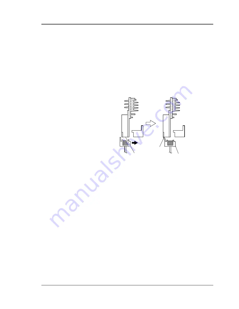
This ejection exhausts heavily viscous ink in the vicinity of the head
nozzle outlet. To do this, the head is moved to the preliminary
discharge position, and the ink is ejected on the absorber in the
restoration tub.
Figure 2-21
Pressurization
When the head is in the capping position, closing the suction pump
and the pressure pump feeds a trace of ink to the head to forcibly
exhaust the in and bubbles inside the head nozzle.
(See “III. INK SUPPLY SYSTEM, 1. Outline of Operation, C.
Operation of the Pressure Mode.”)
Circulation
When the head is in the capping position, driving the pressure pump
and the suction pump to feed ink from the sub-tank to the head.
(See “III. INK SUPPLY SYSTEM, 1. Outline of
Operation, B. Operation of the Circulation Mode.”)
Head
nozzle
face
Cleaner blade
Restration
tub


