Interlogix UltraView PTZ Installation Manual Download Page 26

UltraView PTZ
Installation Manual

16

Flush-mount housings

Flush-mount and pendant-mount housings require different preparation of the mounting surface and different 
installation procedures of the housings. Follow the instructions given here for flush-mount housings. 

Preparing the surface for flush-mounts

Following are the steps for preparing the mounting surface if you are mounting the housing directly into a solid 
surface that does not require reinforcement. If the mounting surface does require reinforcement, first install a 
GEA-113 T-bar ceiling panel or a GEA-114 T-bar support kit. Instructions for installing the GEA-114 are 
available in this manual (

GEA-114 T-bar ceiling support kit

 on page 45). If you are installing a GEA-113, refer 

to the instructions that came with the panel (1052914). 

 To prepare the mounting surface, see 

Figure 12

 and do the following:

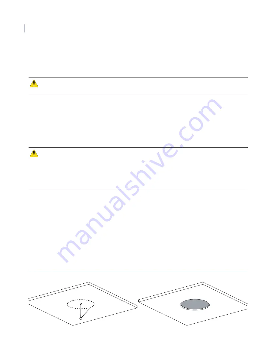
1. Mark the position and size of the housing passthrough hole on the mounting surface. The size of the 

cutout for the passthrough must be 8-3/8 to 8-7/16 in. (21.27 to 21.42 cm).

2. Following all local codes, cut the housing passthrough hole.

3. Make sure that the facility cables (data, video, and power) for the dome comply with the 

recommendations provided in 

Power requirements

 on page 5.

4. Feed the facility cables through the housing passthrough hole in the mounting surface. 

Pull enough cable to make connections. You can always cut off unneeded length later. 

How many cables you have depends upon how many video, data, and power cables you are using. 
See 

Wiring

 on page 19.

Figure 12.Preparing the mounting surface for flush-mount housings being mounted into solid surfaces not requiring reinforcement    

CAUTION:  

The flush-mount housing is for indoor applications only. Do not expose it to moisture, or the unit may  
become damaged. 

CAUTION:  

For all installations, heed these cautions:  

Complete all installation steps before supplying power to the dome.

To ensure proper operation of a PTZ unit, install the mount level.

For safety, the mounting surface, hardware, and procedure used for securing the dome 
must support the weight of the dome, mount (if used), cables, and any structural or environmental
vibration according to local codes. See 

Table 1 

on page 4.

Cutout size:

8-3/8 to 8-7/16 in.

(21.27 to 21.42 cm)

Position and size marked

Summary of Contents for UltraView PTZ

Page 1: ...UltraView PTZ Installation Manual...

Page 2: ...ftware confirms Your agreement to be bound by these terms and conditions If You do not agree with these terms and conditions do not install or use the Software or if already installed immediately ceas...

Page 3: ...Software will be fit for their intended purpose as described in the applicable Documentation from UTC Fire Security and will conform in all material respects to the specifications stated in such Docu...

Page 4: ...C Fire Security and supersedes any proposal or prior agreement oral or written and any other communication relating to the subject matter of this agreement Intended use Use this product only for the p...

Page 5: ...l waste in the European Union For proper recycling return this product to your local supplier upon the purchase of equivalent new equipment or dispose of it at designated collection points For more in...

Page 6: ...UltraView PTZ Installation Manual vi...

Page 7: ...9 Backward compatibility with CyberDome I housings 10 Various mounting and housing styles 10 Wiring best practices 12 Pendant mount wire routing 12 Flush mount wire routing 13 Pendant mount housings 1...

Page 8: ...allation 32 Installing a camera shroud 33 Installing a bubble dome 34 Chapter 5 Troubleshooting maintenance support 37 Troubleshooting 38 Maintenance 39 Cleaning the bubble dome 39 Contacting us 40 On...

Page 9: ...may be found on our website at www interlogix com Note A qualified service person complying with all applicable codes should perform all required hardware installation Conventions used in this docume...

Page 10: ...UltraView PTZ Installation Manual x...

Page 11: ...product contents and system requirements In this chapter Product overview 2 Product contents 2 System requirements 3 Operational requirements 3 Minimum load requirements 4 Cable management 5 Cable req...

Page 12: ...ring the housing addressing the camera site setting the protocol and setting the termination installing the PTZ camera assembly and installing the dome Be aware that the power requirements for CyberDo...

Page 13: ...rolling device is required for operation as shown in Figure 1 In this typical DVR system an operator can pan tilt and zoom the camera find presets and start preset and ShadowTours from the keypad Figu...

Page 14: ...ing arm mount with any dome except heavy duty or flush mount All other dome and mount configurations 50 lb 22 7 kg CAUTION For safety the mounting surface hardware and procedure used for securing the...

Page 15: ...junction box Figure 4 provides an illustration of the cable capacity of three typical applications It is important to note that all cables of the same gauge are not of the same diameter Manufacturer s...

Page 16: ...11 in dia Table 3 Cable requirements Operation Cable requirement Length feet meters Data For RS 422 22 gauge 0 64 mm unshielded two conductor twisted pair UTP cable 10 000 3 000 For RS 485 22 gauge 0...

Page 17: ...gths for an operating voltage of 24 VAC 4 VAC Wire gauge Domes with fan 20 VA Domes with 12 W heater fan x2 45 VA HD domes with 23 W heater fan x2 66 VA AWG mm dia feet meters feet meters feet meters...

Page 18: ...UltraView PTZ Installation Manual 8...

Page 19: ...using styles 10 Wiring best practices 12 Pendant mount wire routing 12 Flush mount wire routing 13 Pendant mount housings 14 Preparing the surface for pendant mounts 14 Installing the housing 14 Flush...

Page 20: ...age 38 to order a new one part number 1046540 Various mounting and housing styles There are three basic mounting styles pendant wall and flush A pendant mount lowers a dome from a ceiling a wall mount...

Page 21: ...Chapter 2 Housings and cables 11 Figure 6 Basic housing styles Flush mount Plastic pendant mount Cast aluminum pendant mount Heavy duty...

Page 22: ...run down through the cable entry hole and the dust seal Take care to avoid damaging the dust seal during installation Note Keep service loops out of housing area when possible Figure 7 Side view of p...

Page 23: ...le entry hole in the side or top of the housing Route the wires through the top or side of the housing and around the camera bracket Note Keep service loops out of housing area when possible Figure 9...

Page 24: ...the dome comply with the recommendations provided in Cable requirements on page 6 3 Feed the facility cables through the pipe in the mounting surface Pull enough cable to make connections You can alwa...

Page 25: ...e pipe or mount Slide the rubber boot down the pipe and fit it securely over the housing s flange For pipe installations thread the housing onto the pipe If necessary first turn the housing counterclo...

Page 26: ...cm 2 Following all local codes cut the housing passthrough hole 3 Make sure that the facility cables data video and power for the dome comply with the recommendations provided in Power requirements on...

Page 27: ...end of the safety cable into the safety clip surrounding the exposed hole inside the housing e Secure the other end of the safety cable to the building superstructure 4 Feed the facility cables throug...

Page 28: ...ed through mount and housing Ceiling ring Ceiling Angle brackets 2 Housing tabs 3 screwed open and down against the mount or Clip for safety cable inside housing Safety cable Building superstructure C...

Page 29: ...PTZ or call Customer Service see Contacting us on page 38 to order a new one part number 1046543 To install a fan on the PTZ unit do the following 1 Slide the slots on the fan bracket onto the mounti...

Page 30: ...pairs CAUTION Do not connect the 24 VAC power cable to the video or RS 422 or RS 485 connection or you will damage the CyberDome Do not supply power to the unit until you have completed the installat...

Page 31: ...me One of the two boards that you will be handling while you wire the dome is inside of the housing In this chapter Components used for basic and advanced operation 22 Wiring the housing board 24 Sett...

Page 32: ...size and length requirements on page 6 The dome uses RS 485 or RS 422 for data communication See Cable requirements on page 6 for more information on limitations Figure 17 Housing board Table 5 on pag...

Page 33: ...of 30 VAC or 30 VDC at 0 5 A Figure 19 Data and alarm contact connectors Low end DPIB only Table 5 UltraViews PTZ housing interface board UTC LED functions Configuration type LED Description UPIB hous...

Page 34: ...Figure 20 Data connections 2 Connect the facility video cable Figure 21 Note Use only crimp on BNC connectors Do not use screw on connectors Figure 21 Video connection If you are installing UTP video...

Page 35: ...r terminal strip If you are using a heavier gauge cable ensure that it is properly seated in the connector Figure 22 Power connection When power is received by the housing board through the power conn...

Page 36: ...o on or off Figure 23 Termination switches To set the termination do the following 1 Set both termination switches to on if the dome or device is the final receiver location for the data signal or if...

Page 37: ...In this chapter Camera assembly preparation and installation 28 Setting the protocol 29 Setting the camera s address 30 Installing the camera assembly 32 Shroud and bubble dome installation 32 Instal...

Page 38: ...ocol DIP switches UltraView PTZ has two multiposition DIP switch blocks one on the upper board and one on the main board of the camera assembly Figure 24 These DIP switches set the communication proto...

Page 39: ...rst log onto the menu system you will be asked which settings you would like to use For more information on protocol functionality with the UltraView PTZ camera see Appendix B Protocol functionality o...

Page 40: ...re 25 for an example 3 Place the switches that correspond to those values in the on position Note A site address can be given a site number from 0 to a maximum of 1023 Figure 25 Address DIP switches s...

Page 41: ...settings for cameras 1 to 64 Unit DIP switch 1 2 3 4 5 6 7 8 9 10 11 12 13 14 15 16 17 18 19 20 21 22 23 24 25 26 27 28 29 30 31 32 Unit DIP switch 33 34 35 36 37 38 39 40 41 42 43 44 45 46 47 48 Unit...

Page 42: ...re the pan tilt assembly by releasing the latch handle and engaging the catch tab 4 Verify that the four mounting nuts mate with the four alignment holes Figure 26 Installing the pan tilt assembly Shr...

Page 43: ...or blocked 2 Using the provided screw attach the shroud to the camera 5 in lb torque 3 Install the dome onto the housing 4 Test the camera s pan and tilt movements to make sure the shroud does not imp...

Page 44: ...ount housing the dome ring contains a foam pad that requires you to push up while turning the screws If you are installing the dome on a rugged vandal resistant housing the screws are tamper resistant...

Page 45: ...ged pendant mount housing and bubble ring Safety clip Safety sable Keylock latch Bubble slots 2 Bubble tabs 2 Safety clip Heavy duty housing and bubble ring Flush mount housing and dome ring Plastic p...

Page 46: ...UltraView PTZ Installation Manual 36...

Page 47: ...mple preventive maintenance procedures and contact technical support in case you need assistance with your Interlogix equipment In this chapter Troubleshooting 38 Maintenance 39 Cleaning the bubble do...

Page 48: ...tor screen If the dome is not powered or the programming is not running properly remove and reinstall the camera assembly See Camera assembly shroud bubble dome on page 25 If the video still does not...

Page 49: ...To remove heavier contaminants rinse the dome with water and immediately dry it with clean dry pressurized air to prevent water spots To remove stubborn contaminants use a wick to clean the dome s su...

Page 50: ...ance with your Interlogix product is our online publication library To access the library go to our website at the following location http www interlogix com1 Table 9 Sales and support contact informa...

Page 51: ...mount arm and a T bar support kit Instructions for all other mounts arms adapters and brackets are shipped with those mounts In this appendix GEA 102 wall mount arm 42 Installing the wall mount arm 42...

Page 52: ...e rear opening in the base If the cables are attached externally to the mounting surface and need to enter the arm through the side open a conduit hole in the side of the arm with the instructions giv...

Page 53: ...ed the cables through the cable entry hole in the mounting surface or through the conduit attached to the opened conduit hole and up through the arm Pull enough cable to make connections You can alway...

Page 54: ...11 Before you attach the housing to the arm attach the housing safety cable to the arm safety chain Figure 35 Note The safety cable for rugged housings is metal and for plastic housings is a beaded c...

Page 55: ...to bring the facility cables in through the side of the arm To open the conduit hole see Figure 36 on page 46 and do the following 1 Locate the dimple on the side of the arm 2 Drill a 3 8 in 10 mm pi...

Page 56: ...UltraView PTZ Installation Manual 46 Figure 36 Opening a conduit hole Pilot hole Enlarged hole 3 8 in 10 mm For 3 4 in conduit 1 7 64 in 28 mm For 1 2 in conduit 7 8 in 22 mm...

Page 57: ...instructions To install a T bar ceiling support kit see the corresponding figures and do the following 1 Remove the removable ceiling panel where the flush mount housing will be installed 2 Center th...

Page 58: ...le Drill cut all holes perpendicular to the panel and be careful not to overcut the housing passthrough hole 5 Reset the angle brackets and ceiling ring on the removable ceiling panel aligning the cen...

Page 59: ...bar support kit 9 Return to Installing the housing on page 15 to finish installing the dome Flush mount housing Ceiling ring Angle brackets Removable ceiling panel Viewed from side shown with housing...

Page 60: ...UltraView PTZ Installation Manual 50...

Page 61: ...Appendix B Protocol functionality This appendix provides information on protocol functionality In this appendix UltraView PTZ protocol functionality 52 Equipment protocol testing list 56...

Page 62: ...33 Run pattern learn number 1 See Pelco keypad documentation Set left limit stop Preset 92 Set right limit stop Preset 93 Enter into menu mode Preset 95 Begin frame scan Preset tour number 1 Preset 9...

Page 63: ...a mimic tour See VCL keypad documentation Table 13 Vicon commands supported Command Note Set preset out of GUI See Vicon keypad documentation Go to preset XX See Vicon keypad documentation Enter into...

Page 64: ...Run learn tour 3 1 9 5 CAM FUNCTION Run learn tour 4 1 9 6 CAM FUNCTION Program learn tour 1 CAMERA SETUP PATROL LEARN or 1 6 7 CAM FUNCTION Program learn tour 2 1 9 7 CAM FUNCTION Program learn tour...

Page 65: ...preshot 88 Run preset tour 3 Continuous vectorscan 3 or preshot 89 Run preset tour 4 Continuous vectorscan 4 Autopan Continuous vectorscan 0 Day night toggle Preshot 99 or preshot 94 or nightshot mode...

Page 66: ...autobaud MPT9500 2400 baud KBD300 4800 baud PC 9600 baud Pelco P autobaud KBD300 4800 baud PC 2400 9600 baud Ultrak 9600 baud Diamond JPD101 or Honeywell HJZTP VCL Ademco ADCJA or Honeywell HJZTP Vico...

Page 67: ...tocol 29 dome configurations 4 domes 34 H housings 2 aluminum pendant mount 10 flush mount 10 16 18 heavy duty 4 10 mounting styles 10 pendant mount 10 14 15 plastic pendant mount 10 K keypad 3 L LEDs...

Page 68: ...er cable size and length 7 system 3 S safety cautions cables 24 captive screws 34 35 dome 34 heaters 24 installation 14 16 42 47 load 4 15 17 moisture 14 16 power supplies 5 safety terms and symbols i...

Reviews: