background image


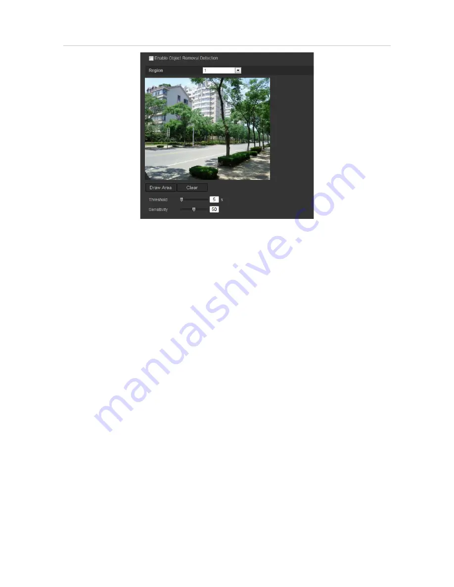
Figure 20: Object removal detection window 


To define object removal detection: 

1.  From the menu toolbar, click 

Configuration

 > 

Smart Event

 > 

Object Removal 

Detection.


2.  Select the 

Enable Unattended Baggage Detection

 check box to enable the 

function.  

3.  Click 

Draw Area

, and then draw a rectangle on the image as the designated region.  

When you draw the rectangle, all lines should connect end-to-end to each other. Up 
to four areas are supported. Click 

Clear

 to clear the areas you have drawn. The 

designated region parameters can be set up separately. 

Note

: The area can only be quadrilateral.  

4.  Choose the region to be configured. 

Threshold: 

the threshold for the time of the objects removed from the region. If you 

set the value as 10, alarm is triggered after the object is removed and absent from 
the region for 10s. The range is 5 and 20s. 


Sensitivity:

 The sensitivity value defines the size of the object that can trigger the 

alarm. When the sensitivity is high, the removal of a small object can trigger the 
alarm. The range is between 1 and 100. 

5.  Click

 Edit 

to set the arming schedule for the alarm input. See “Motion detection 

alarms” on page 30 for more information. 

6.  Specify the linkage method when an event occurs. Select one or more response 

methods for the system when an object removal alarm is triggered. 


56 

TruVision Stainless Steel IP Cameras Configuration Manual 

Summary of Contents for TruVision TVD-5801

Page 1: ...TruVision Stainless Steel IP Cameras Configuration Manual P N 1073371 EN REV B ISS 27MAR18...

Page 2: ...laimers THESE PRODUCTS ARE INTENDED FOR SALE TO AND INSTALLATION BY QUALIFIED PROFEIONALS UTC FIRE SECURITY CANNOT PROVIDE ANY AURANCE THAT ANY PERSON OR ENTITY BUYING ITS PRODUCTS INCLUDING ANY AUTHO...

Page 3: ...rms 30 Tamper proof alarms 36 Exception alarms 37 Alarm inputs and outputs 38 Face detection 39 Audio exception detection 41 Cross line detection 42 Intrusion detection 44 Defocus detection 46 Scene c...

Page 4: ...ration file 70 Upgrade firmware 70 Reboot camera 71 Camera operation 72 Logging on and off 72 Live view mode 72 Playing back recorded video 73 Searching event logs 75 Operating PTZ control 77 2 TruVis...

Page 5: ...s with a user account with administrative rights for configuring all options on the camera The user name is admin and the password is 1234 For enhanced security we highly recommend changing the defaul...

Page 6: ...ck Internet Options on the Tools menu 2 On the Security tab click the zone to be assigned to a website under Select a web content zone to specify its security settings 3 Click Custom Level 4 Change th...

Page 7: ...Activation window appears You must define a high security admin password before you can access the camera There is no default password provided You can activate a password via a web browser and via Tr...

Page 8: ...Activation via TruVision Device Manager For instructions on how to activate the camera using TruVision Device Manager refer to the TruVision Device Manager User Manual Go to www interlogix com video p...

Page 9: ...lt unit light or wiper is installed 9 Display Control Click each tab to adjust the layout and the stream type of the live view You can also click the drop down menu to select the plug in For IE intern...

Page 10: ...ation panel to configure the network camera settings alarms users transactions and other parameters such as upgrading the firmware See Figure 2 below for descriptions of the configuration menus availa...

Page 11: ...focus Detection Scene Change Detection Face Detection Cross Line Intrusion Detection Region Entrance Detection Region Exiting Detection Unattended Baggage Detection and Object Removal Detection 8 Stor...

Page 12: ...etected the face will be marked with a green frame in Live View 4 Image Format Choose the image format for a snapshot JPEG or BMP Record File Settings 5 Record File Size Specifies the maximum file siz...

Page 13: ...3 Under Time Sync select one of the options for setting the time and date Synchronize with an NTP server Select NTP and type the server NTP address The time interval can be set from 1 to 10080 minutes...

Page 14: ...nd other network settings from that server IPv4 Address Enter the IPv4 address of the camera IPv4 Subnet Mask Enter the IPv4 subnet mask IPv4 Default Gateway Enter the IPv4 gateway IP address IPv6 Mod...

Page 15: ...a service that maps Internet domain names to IP addresses It is designed to support dynamic IP addresses such as those assigned by a DHCP server Specify IP Server DynDNS or ezDDNS DynDNS Dynamic DNS M...

Page 16: ...ype IPv4 settings IPv6 settings MTU settings and Multicast Address 3 If a DHCP server is available select DHCP 4 If the DNS server settings are required for some applications e g sending email you sho...

Page 17: ...e PPPoE to enable this feature 3 Enter User Name Password and Confirm password for PPPoE access 4 Click Save to save changes To define the SNMP parameters 1 From the menu toolbar click Configuration N...

Page 18: ...Configure the FTP settings including server address port user name password directory and upload type Anonymous Select the check box to enable the anonymous access to the FTP server Directory In the...

Page 19: ...f it is required by the SMTP server Attached Snapshot Select the check box of Attached Snapshot if you want to send emails with attached alarm images Interval This is the time between two actions of s...

Page 20: ...meters 4 Click Save to save changes To set up the NAT parameters 1 Click Configuration Network NAT 2 Select the check box to enable the NAT function 3 Select Port Mapping Mode to be Auto or Manual Whe...

Page 21: ...mit it to the trusted certificate authority for signature such as Symantec or RSA After receiving the signed valid certificate upload the certificate to the device Recording parameters You can adjust...

Page 22: ...e or fixed bit rate is used Variable produces higher quality results suitable for video downloads and streaming Default is Constant Video Quality Specifies the quality level of the image It can be set...

Page 23: ...ental Noise Filter Set it as OFF or ON Enable the function to filter background ambient noise 3 ROI Enable to assign more encoding resources to the region of interest to increase the quality of the RO...

Page 24: ...and search the objects or people crossing this virtual line Note Only cross line and intrusion detection can support dual VCA mode To define Dual VCA parameters 1 In the Video Audio panel click the D...

Page 25: ...tion 1 Switch Day and Night Settings Auto D N Switch The camera automatically switches between day and night mode All image settings remain the same for both modes Scheduled D N settings The camera sw...

Page 26: ...s Level Select the iris level default is 50 Exposure Time The exposure time controls the length of time that the aperture is open to let light into the camera through the lens Select a higher value if...

Page 27: ...the camera Based on this information the camera will continue to display all colors correctly even when the color temperature of the scene changes such as from daylight to fluorescent lighting Select...

Page 28: ...dard 50 Hz and 60 Hz are selectable Choose according to the different video standards normally 50 Hz for PAL standard and 60 Hz for NTSC standard Capture Mode Set the required frame rate to meet the d...

Page 29: ...des include Transparent Not flashing The image appears through the text Transparent Flashing The image appears through the text The text flashes on and off Not transparent Not flashing The image is be...

Page 30: ...window to adjust the text overlay position 5 Repeat steps 2 to 4 for each extra line of text selecting the next string number Note Remove an overlay text by deselecting its text line 6 Click Save to s...

Page 31: ...raw up to four areas on the same image 5 Click Stop Drawing to finish drawing or click Clear All to clear all of the areas you set without saving them 6 Click Save to save changes Picture overlay Pict...

Page 32: ...ects motion However the motion alarm is only triggered if it occurs during a programmed time schedule Select the level of sensitivity to motion as well as the target size so that only objects of inter...

Page 33: ...ee Figure 10 item 2 3 Recording schedule Define the schedule during which motion detection will be recorded See Recording schedule on page 61 for further information 4 Linkage Specify the method of re...

Page 34: ...drag the mouse on the live video image to draw an area sensitive to motion detection Note You can draw up to 8 motion detection areas on the same image 5 Click Stop Drawing to finish drawing Click Cle...

Page 35: ...on To upload the snapshot to FTP and NAS when motion detection or an alarm input is triggered you must also enable Enable Event triggered Snapshot under the snapshot parameters See Snapshot parameters...

Page 36: ...same image 6 Click Stop Drawing to finish drawing Click Clear All to delete all areas marked and restart drawing 7 Move the Sensitivity slider to set the sensitivity of the detection for the selected...

Page 37: ...is triggered and upload the snapshot to NAS or FTP server Note To upload the snapshot to NAS you must first configure the NAS settings See NAS settings on page 59 for further information To upload the...

Page 38: ...m response action Figure 11 Tamper proof alarm window To set up tamper proof alarms 1 From the menu toolbar click Configuration Basic Event Tamper proof 2 Select Enable Tamper proof 3 Move the Sensiti...

Page 39: ...Output Trigger external alarm outputs when an event occurs Select Select All or each individual alarm output Note This option is only supported by cameras that feature an alarm output 6 Click Save to...

Page 40: ...mation Enable the Upload Type option To upload the snapshot to FTP and NAS when motion detection or an alarm input is triggered you must also enable Enable Event triggered Snapshot under the snapshot...

Page 41: ...ers the recording to start in the camera Trigger Alarm Output Trigger external alarm outputs when an event occurs Select Select All or each individual alarm output Note This option is only supported b...

Page 42: ...t the detected face marked with the green frame select Disable from Configuration Local Configuration Live View Parameters Rules 4 Configure the sensitivity of the face detection The range is between...

Page 43: ...apshot to an FTP you must first configure the FTP settings See To define the FTP parameters on page 16 for further information Enable the Upload Type option To upload the snapshot to FTP and NAS when...

Page 44: ...the higher the value Adjust it according to the actual environment The range is between 1 and 100 5 Click Edit to set the arming schedule for the alarm input See Motion detection alarms on page 30 for...

Page 45: ...row on the B side is displayed When an object moves across the plane in both directions it is detected and alarms are triggered A B Only an object crossing the pre defined line from the A to the B sid...

Page 46: ...o an FTP you must first configure the FTP settings See To define the FTP parameters on page 16 for further information Enable the Upload Type option To upload the snapshot to FTP and NAS when motion d...

Page 47: ...is is the time threshold that the object remains in the region If you set the value as 0 the alarm is triggered immediately after the object enters the region The range is between 0 and 100 Sensitivit...

Page 48: ...e the Upload Type option To upload the snapshot to FTP and NAS when motion detection or an alarm input is triggered you must also enable Enable Event triggered Snapshot under the snapshot parameters S...

Page 49: ...specified address when there is an alarm Note You must configure email settings before enabling this option See To set up the email parameters on page 17 for further information If you want to send th...

Page 50: ...sensitivity ranging from 1 to 100 the higher the sensitivity the easier the change of scene can trigger the alarm 3 Click Edit to set the arming schedule for the alarm input See Motion detection alarm...

Page 51: ...configure the FTP settings See To define the FTP parameters on page 16 for further information Enable the Upload Type option To upload the snapshot to FTP and NAS when motion detection or an alarm inp...

Page 52: ...Clear to clear the areas you have drawn The designated region parameters can be set up separately Note The area can only be quadrilateral 5 Set the sensitivity level The sensitivity value defines the...

Page 53: ...re the FTP settings See To define the FTP parameters on page 16 for further information Enable the Upload Type option To upload the snapshot to FTP and NAS when motion detection or an alarm input is t...

Page 54: ...drawn The designated region parameters can be set up separately Note The area can only be quadrilateral 4 Choose the region to be configured Sensitivity The sensitivity value defines the size of the...

Page 55: ...ings See To define the FTP parameters on page 16 for further information Enable the Upload Type option To upload the snapshot to FTP and NAS when motion detection or an alarm input is triggered you mu...

Page 56: ...quadrilateral 4 Choose the region to be configured Threshold the threshold for the time the objects remain left in the region If you set the value as 10 an alarm is triggered after the object is left...

Page 57: ...the FTP settings See To define the FTP parameters on page 16 for further information Enable the Upload Type option To upload the snapshot to FTP and NAS when motion detection or an alarm input is trig...

Page 58: ...4 Choose the region to be configured Threshold the threshold for the time of the objects removed from the region If you set the value as 10 alarm is triggered after the object is removed and absent f...

Page 59: ...o start in the camera Trigger Alarm Output Trigger external alarm outputs when an event occurs Select Select All or each individual alarm output Note This option is only supported by cameras that feat...

Page 60: ...me interval between two snapshots Select the unit of time from the drop down list milliseconds seconds minutes hour or day 6 Set the schedule for when you want snapshots to be taken Click Edit and ent...

Page 61: ...settings You can use a network attached storage NAS device to remotely store recordings To configure recording settings please ensure that you have the network storage device within the network The NA...

Page 62: ...ing Once formatting is completed reboot the camera otherwise the device will not function properly If Overwrite is enabled the oldest files are overwritten when the storage becomes full Figure 18 Stor...

Page 63: ...record 5 s 10 s 15 s 20 s 25 s 30 s or Not Limited Post record time The post record time is set to stop recording after the scheduled time or the event For example if an alarm triggered recording ends...

Page 64: ...a person or object enters the pre defined area Region exiting detection Video is recorded when a person or object leaves the pre defined area Unattended baggage detection Video is recorded when the o...

Page 65: ...click Configuration Counting 2 Select the Enable Object Counting check box to enable the function 3 Select the Enable OSD Overlay check box The real time number of people entered and exited is superim...

Page 66: ...and Annual report Daily report calculates the data on the selected date Weekly report calculates for the week of the selected date Monthly report calculates for the month of the selected date Annual r...

Page 67: ...elow Figure 19 User management window Passwords limit access to the camera and the same password can be used by several users When creating a new user you must give the user a password There is no def...

Page 68: ...dd button The user management window appears 3 Enter a user name 4 Assign the user a password Passwords can have up to 16 alphanumeric characters 5 Select the type of user from the drop down list The...

Page 69: ...n You can easily change the information about a user such as their name password and permissions To modify user information 1 Select the required user under the User tab 2 Click the Modify button The...

Page 70: ...the IP address of the server hosting the video management software is allowed to be accessed and attempts by users at any other IP addresses would be denied access Figure 21 IP address filter window T...

Page 71: ...user name password attempts 10 attempts for the operator user 2 If the IP address is locked you can try to login the device after five minutes To define SSH 1 Click Configuration Security Security Se...

Page 72: ...e saving path to save the configuration file Upgrade firmware The camera firmware is stored in the flash memory Use the upgrade function to write the firmware file into the flash memory You need to up...

Page 73: ...instructions in the TruVision Device Manager User Manual ensure that the firmware update file has already been downloaded to the local computer To access the TruVision Device Manager User Manual go t...

Page 74: ...pon first use for enhanced security Live view mode Once logged in click Live View on the menu toolbar to access live view mode See Figure 1 on page 6 for the description of the interface Start stop li...

Page 75: ...ayback click Playback on the menu toolbar The Playback window displays See Figure 24 on page 73 Figure 24 Playback window Name Description 1 Playback button Click to open the Playback window 2 Search...

Page 76: ...Control playback Click to control how the selected file is played back play stop slow and fast forward playback To play back recorded video 1 Select the date and click the Search button The searched v...

Page 77: ...be able to use the log functions The number of event logs that can be stored on NAS or SD card depends on the capacity of the storage devices When this capacity is reached the system starts deleting...

Page 78: ...can be searched by start and end recording time Table 1 Types of logs Main log type Minor log types Description of events included Alarm Alarm Input Alarm output Start Motion Detection Stop Motion De...

Page 79: ...g 4 Click Search to start your search The results appear in the left window Operating PTZ control for supported cameras only In the live view interface you can use the PTZ control buttons to control p...

Page 80: ...finish the setting of the current preset 4 You can click to delete the preset To call a preset 1 Select a defined preset from the list 2 Click to call the preset Using preset tours A preset tour is a...

Page 81: ...set Tour Speed The speed the camera moves from one preset to another 5 Click OK to save a preset into the preset tour 6 Repeat the steps from 3 to 5 to add more presets 7 Click to save all the preset...

Page 82: ...to audio exception alarm 42 link to camera defocus detection alarm 47 link to camera tamper alarm 37 link to cross line detection alarm 44 link to exception alarms 38 link to face detection alarm 41...

Page 83: ...s in live view mode 72 RS 485 settings 63 RTSP authentification 67 S SDHC card capacity 60 formatting 60 Snapshots archive snapshots from recorded files 74 event triggered 57 save during live view mod...

Reviews: