background image

Chapter 1 - Getting Started          9

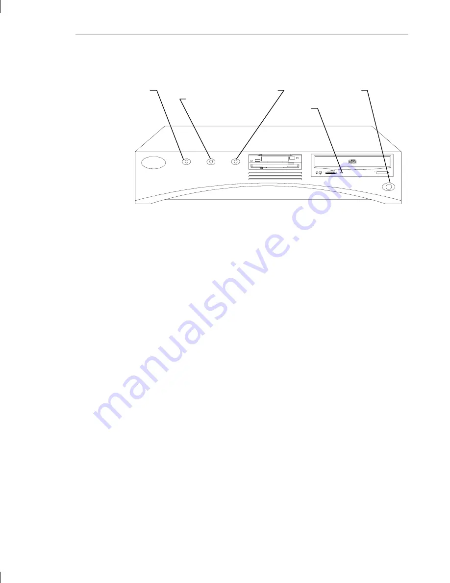
The following figure shows the front of the base unit.

 To start the system:

1.

Press the power switch on the base unit and the power switch on the
monitor to turn on power to the system.  The following events occur:

♦ 

The power on LED lights green.

♦ 

The CD-ROM drive LED blinks green and amber.

♦ 

The BIOS boot screen displays the American Megatrends logo.

♦ 

The boot screen displays.

2.

At the initial Windows NT boot screen, select the following option:

Windows NT Workstation 3.51 [VGA Mode]

After additional messages display, Windows NT Workstation starts in
VGA mode, allowing you to log on and configure your system’s date,
time, and video display.

3.

Press 

CTRL

+

ALT

+

DELETE

 to display the Windows NT Workstation

logon dialog.  The first time the logon dialog displays,

Administrator

 displays in the Username box.  The From and

Password boxes are blank.

4.

Select OK or press 

ENTER 

to log on to Windows NT Workstation.  For

instructions to create a user account and join a workgroup or domain,
refer to the online Windows NT Workstation System Guide.

Reset   

  Disk

Power 

             Power

Switch   

  Activity

On LED  

             Switch

  LED

       CD-ROM
       LED

Summary of Contents for TDZ-300

Page 1: ...TDZ 300 TDZ 400 Desktop Setup and Maintenance Guide March 1996 ...

Page 2: ...graph Corporation including this documentation and any software and its file formats and audio visual displays described herein all rights reserved may only be used pursuant to the applicable software license agreement contains confidential and proprietary information of Intergraph and or other third parties which is protected by copyright trade secret and trademark law and may not be provided or ...

Page 3: ... the appropriate safety approvals for the country in which the equipment will be installed and marked HAR FCC Statement This equipment has been tested and found to comply with the limits for a Class A digital device pursuant to part 15 of the FCC Rules These limits are designed to provide reasonable protection against harmful interference when the equipment is operated in a commercial environment ...

Page 4: ...RE Read all safety and operating instructions before using the equipment Keep these instructions for future reference Follow all warnings on the equipment or in the operating instructions Warnings To reduce the risk of electrical shock do not attempt to open the equipment unless instructed Do not use a tool for purposes other than instructed There are no user serviceable parts in the power supply ...

Page 5: ...ystem 8 Observing System Precautions 10 Using the Online Reference 11 Obtaining Windows NT Updates 12 Ensuring PC Card Support 13 Chapter 2 Configuring the System 15 Before You Begin 15 About the System s Video Display 16 Configuring the Video Display 17 Starting and Stopping Video Configuration 17 Changing GL Video Display Configuration 19 Changing the Default Video Display Driver 21 Correcting V...

Page 6: ...ading the System 55 Adding Main Memory 55 Internal SCSI Devices 58 External SCSI Devices 60 Adding Option Boards 61 PCI Option Boards 62 ISA and PnP Option Boards 63 Using the System Configuration Utility 65 ISA Boards with a Configuration File 66 ISA Boards without a Configuration File 67 Chapter 6 GLZ Graphics 71 Replacing Graphics Boards 71 GLZ1 and GLZ3 72 GLZ1T and GLZ5 73 GLZ2 74 Geometry Ac...

Page 7: ... 97 Appendix B Hardware Infomration 103 External Ports 103 MIDI Game 103 Ethernet AUI 104 SCSI 105 Serial COM 106 Ethernet 10Base T 106 Parallel 107 Video 108 Mouse and Keyboard 108 System Board Connector Pinouts 109 Floppy 110 ISA Bus J3 110 ISA Bus J6 111 Audio 111 System Board Jumper Connectors 112 G95 VGA Mode Disable Enable 112 Vibra 16S Sound Disable Enable 112 CPU Frequency 113 Power Supply...

Page 8: ...viii Preface Returned Goods Authorization RGA Form Warranty Procedure Repair Depot Address Labels ...

Page 9: ...tworking software Chapter 3 Opening and Closing the Base Unit describes how to open and close the system for maintenance and upgrades Chapter 4 Maintaining the System describes how to maintain the system and replace its major components and how to reprogram the system s flash EPROM Chapter 5 Upgrading the System describes how to upgrade the system with new components Chapter 6 GLZ Graphics describ...

Page 10: ...d line in lowercase unless directed otherwise SMALL CAPS Key names on the keyboard such as D ALT or F3 CTRL D Press a key while simultaneously pressing another key for example press CTRL and D simultaneously Finding Operating System Information For more information on using the Windows NT operating system refer to the printed and online Windows NT documentation from Microsoft For detailed informat...

Page 11: ...ergraph systems and products or to enroll in an available class contact Intergraph Education Services at 1 800 240 3000 Getting Telephone Support If you experience problems with your Intergraph system or software or have questions about the information in this document you can contact Intergraph for help In the United States call the Customer Response Center at 1 800 633 7248 between the hours of ...

Page 12: ...ions protocol for eight 8 data bits no parity one 1 stop bit and any baud rate up to 14 400 2 Using a modem dial the IBBS number 1 205 730 8786 You can dial 1 205 730 6504 if you are using a 2 400 baud connection 3 Mirror sites are maintained for international locations Information on these sites is available on Intergraph Online Intergraph s World Wide Web server Refer to Finding Intergraph on th...

Page 13: ...Intergraph on the Internet in the following ways If you have a World Wide Web browser connect to Intergraph Online Intergraph s Web server at http www intergraph com If you have an application that allows you to transfer files to and from a system using File Transfer Protocol FTP connect to Intergraph s anonymous FTP site at ftp intergraph com If you have an application that allows you to search a...

Page 14: ... About System Ergonomics Please read the Ergonomics Guide included with your Intergraph system This document provides valuable information on ways to minimize repetitive stress injuries for persons working with a computer ...

Page 15: ...base unit Keyboard Mouse Footstands Base unit power cord Operating system and system software carton The carton for the operating system and system software contains the folllowing items Windows NT software CD ROM and setup diskettes Intergraph GL video display driver diskette Intergraph Quick Fix Engineering QFE diskette Intergraph System Utilities SYSUTIL diskette Intergraph TDZ 300 TDZ 400 Desk...

Page 16: ...it in an area where air can circulate freely around it The back panel of the base unit should have at least a 3 inch clearance and the sides should have at least a 1 inch clearance unless the base unit is set in the vertical position Do not expose the system to high levels of dust smoke or moisture Place the system in an area where the temperature range stays between 10 C and 26 C 50 F to 80 F The...

Page 17: ...irflow you must use the footstands when setting the base unit in the vertical position Note Ensure the power switch is at the top when setting the base unit in the vertical position 2 Connect the keyboard cable to the Keyboard port on the back of the base unit Refer to the following figure Power Switch ...

Page 18: ...Ethernet AUI or 10Base T ports printer parallel port and modem cables COM1 and COM2 ports to their ports on the back of the base unit Refer to the following figure WARNING If you are using cables not supplied by Intergraph you must use shielded cables to prevent excessive electromagnetic interference EMI Intergraph cables are designed to reduce the amount of EMI produced by the system Note The por...

Page 19: ... for the monitor and base unit to an Uninterruptible Power Supply UPS or a grounded three prong wall outlet Then connect the power cords to the base unit and the monitor 9 Connect the video cables as described in Connecting the Video Cables 10 Start the system as described in Starting the System Connecting the Video Cables This section describes the video cable hookups for systems using GLZ1 GLZ1T...

Page 20: ...AUTION Do not connect the video cables for the monitors to either VGA Loopback port If you do the system will boot up to the blue screen and stop or video will not display at all Video Port Video Port Secondary Monitor Video Port Primary Monitor VGA Loopback Ports VGA Loopback Ports ...

Page 21: ... to the monitor Refer to the following figure 2 Connect the VGA loopback cable to the VGA Loopback ports on the back of the base unit Refer the following figure CAUTION Do not connect the video cable for the monitor to either VGA Loopback port If you do the system will boot up to the blue screen and stop or video will not display at all Video Port VGA Loopback Ports ...

Page 22: ...ivered with the operating system installed on the system s hard disk drive After setting up the system you can start it and begin using it Note If you need to re install the operating system refer to Appendix A Installing System Software WARNING If the AC voltage switch on the back of the base unit is not set correctly for your location the workstation will be seriously damaged when the power swit...

Page 23: ...g option Windows NT Workstation 3 51 VGA Mode After additional messages display Windows NT Workstation starts in VGA mode allowing you to log on and configure your system s date time and video display 3 Press CTRL ALT DELETE to display the Windows NT Workstation logon dialog The first time the logon dialog displays Administrator displays in the Username box The From and Password boxes are blank 4 ...

Page 24: ...p for information on creating an Emergency Repair Disk and to the Windows NT Workstation Installation Guide for information on using it Note If your system came pre configured from Intergraph you can run the Repair Disk utility from an icon in the Startup group of Program Manager Observing System Precautions Observe the following precautions when using the system When restarting the system use the...

Page 25: ...al information about your workstation is delivered in an Online Reference document This Windows Help based document is delivered on diskette in the form of a self extracting archive file named TDZDTOR EXE To install and display your system s Online Reference 1 Insert the diskette containing the Online Reference into the floppy diskette slot of the combo drive 2 Copy the TDZDTOR EXE and README TXT ...

Page 26: ...h Product Centers Systems and Networking File Libraries Technical Notes From the FTP login go to bbs ssd note 2 Look for self executing EXE archive files whose names start with TD and end in OR such as TDZDTOR EXE or TDZDSOR EXE The file descriptions in the IBBS or the FTP index should note the title and part number of each Online Reference 3 Download the file to your system 4 Open the EXE file an...

Page 27: ...s described with the announcement of its availability If you obtain a Service Pack from any other source be aware that it may not have been certified with your Intergraph hardware Ensuring PC Card Support Your system may have a PC Card slot for use with devices based on standards developed by the Personal Computer Memory Card International Association PCMCIA Windows NT Workstation 3 51 provides su...

Page 28: ...14 Chapter 1 Getting Started ...

Page 29: ... IP subnet mask for your system IP domain name for your network IP address for your network s default gateway IP addresses for your network s Domain Name System DNS servers if any The Windows NT delivery media contain software and drivers for both Reduced Instruction Set Computing RISC and Intel based systems When installing Windows NT distribution files make sure to install them from the I386 dir...

Page 30: ...mapping GLZ2 24 MB of frame buffer memory resolutions up to 1600 x 1280 GLZ3 same features as GLZ1 with support for geometry acceleration GLZ4 same features as GLZ2 with support for geometry acceleration GLZ5 same features as GLZ3 with support for texture mapping GLZ6 34 MB of frame buffer memory hardware accelerated support for texture mapping and geometry acceleration resolutions up to 1600 x 12...

Page 31: ...chapter Configuring the Video Display Use Intergraph s Video Configuration application in the Windows NT Control Panel to change the configuration of the GL video display driver The Video Configuration application controls basic and advanced display attributes of the GL video display driver Note Windows NT provides a Display application in the Control Panel for changing the video display Use the V...

Page 32: ...Default Video Display Driver later for more information Note the following about the operation of Video Configuration Supported options display in black unsupported options display in gray If a video display driver is not running the main dialog of Video Configuration tells you that certain options may not be supported Any changes you make using Video Configuration are updated in the Windows NT Di...

Page 33: ...3 and GLZ5 only support multi sync monitors and this option is unavailable for selection Note By default the GL video display driver should determine the type of monitor connected to the system by querying the monitor if an InterVue monitor is connected to the system 6 Select Dual if applicable This enables Orientation and Style 7 Select the screen display orientation if applicable 8 Select the sc...

Page 34: ... to the Video Configuration dialog 11 Select Color Calibration to display the Color Calibration dialog and set the contrast and gamma correction value s 12 Select the screen to modify if applicable 13 Move the Contrast scroll bar to set the contrast value The default contrast value is 100 14 Select a Gamma Correction option and choose the value or specify a gamma correction file 15 If you selected...

Page 35: ...ull Drag check box 3 Select OK Windows NT lets you use software cursors such as decorated or animated cursors in place of the standard cursor If you use a software cursor while running an OpenGL application the performance of that application will drop sharply whenever you position the software cursor in that application s window For optimum performance of OpenGL applications Intergraph recommends...

Page 36: ...If using the Last Known Good option fails to correct the video display problems you can obtain a functional video resolution by restarting the system in VGA mode To restart the system in VGA mode 1 Press the Reset button on the front panel of the base unit to restart the system 2 At the boot screen select the following option Windows NT Workstation 3 51 VGA mode After logging on to Windows NT in V...

Page 37: ...TCP IP networking software 1 Open Network in the Windows NT Control Panel The Network Settings dialog displays 2 Select Change next to the Computer Name field The Computer Name dialog displays 3 Type a name for the computer and select OK 4 If appropriate select Change next to the Workgroup field The Domain Workgroup Settings dialog displays 5 Type a new workgroup name and select OK 6 Select TCP IP...

Page 38: ...24 Chapter 2 Configuring the System 10 In the TCP IP Configuration dialog select OK 11 Restart the system ...

Page 39: ...s to avoid electrostatic discharge and attaching an antistatic wrist strap Removing the Top Cover WARNING Before opening the base unit turn the system power off Use caution when removing the top cover to avoid injury To remove the top cover 1 Pull the plunger out and rotate it to lock it in the open position Plunger ISA I O Panel ...

Page 40: ... Terminator Card Power Supply 4 Take precautions to avoid electrostatic discharge as described in the next section whenever the base unit is open Avoiding Electrostatic Discharge Some of the sensitive components inside the base unit can be damaged by static electricity To minimize this possibility take the following precautions when working with the internal components of the system to avoid elect...

Page 41: ...hing an Antistatic Wrist Strap Use a disposable or reusable antistatic wrist strap when servicing or upgrading the workstation Note There is no increased risk of electrical shock when using an antistatic wrist strap If the wrist strap does not snugly contact bare skin static protection will not be effective To attach a disposable antistatic wrist strap 1 Remove the wrist strap from the envelope 2 ...

Page 42: ...Slip the elastic end of the wrist strap snugly around your bare wrist Note The metal conductor bead in the elastic must contact bare skin Replacing the Top Cover Replacing the top cover is almost as easy as removing it Follow these quick steps To replace the top cover 1 When closing the system disconnect the wrist strap from the metal inside the base unit Ground Loop ...

Page 43: ...e Unit 29 2 Replace the top cover by aligning the tabs on the front of the top cover with the notches behind the faceplate 3 Lower the back of the top cover and slide it into place 4 Turn the plunger to lock the top cover to the base unit ...

Page 44: ...30 Chapter 3 Opening and Closing the Base Unit ...

Page 45: ...t and a clean cloth to clean the monitor screen and the exterior surfaces of the base unit Mouse On the bottom of the mouse a retaining ring holds the tracking ball in place To clean the mouse remove the retaining ring and turn the mouse over the tracking ball will fall out Blow gently into the opening Clean the tracking ball and rollers with a cotton swab and alcohol Replace the tracking ball and...

Page 46: ...xteenth inch nutdriver Five sixteenth inch or 8 mm nutdriver Small single slot screwdriver Open the base unit take precautions against electrostatic discharge and attach an antistatic wrist strap as described in Chapter 3 Opening and Closing the Base Unit before replacing any parts After replacing system parts close the base unit as described in Chapter 3 CAUTION The parts inside the base unit are...

Page 47: ...ombo drive 1 Lift the combo drive out of the base unit and disconnect the ISA bus cables power cable and floppy cable Note the position of pin 1 identified by the red stripe on the floppy cable as shown Floppy Cable Combo Drive ISA Bus Cables Power Cable Red Stripe ...

Page 48: ... install the new combo drive 1 Mount the replacement combo drive to the support bracket using the four screws removed previously 2 Connect the ISA bus cables power cable and floppy cable to the combo drive 3 Slide the combo drive through the faceplate Ensure the bracket fits into the peripheral brace 4 Close the base unit Screws Support Bracket ...

Page 49: ... cable SCSI cable and audio cable from the CD ROM drive as shown in the following figure 3 Disconnect the audio cable from the system board connector 4 Using a No 1 Phillips screwdriver remove the four Phillips screws holding the CD ROM drive to the support bracket 5 Remove the CD ROM drive from the base unit by pushing it through the face plate CD ROM Drive SCSI Cable Audio Cable Power Cable ...

Page 50: ...sertion so that the red stripe pin 1 is adjacent to the power connector 5 If installing an Intergraph CD ROM drive the audio cable is already connected to the drive Connect the loose end of the audio cable to its system board connector Note If installing a non Intergraph CD ROM drive use the audio cable delivered with the new CD ROM drive 6 Replace the combo drive 7 Close the base unit System Hard...

Page 51: ...Chapter 4 Maintaining the System 37 3 Using a No 2 Phillips screw driver remove the power switch cable from the chassis Power Switch Cable Ground Wire Screw ...

Page 52: ...wdriver remove the other two screws and grommets from the side of the hard disk drive To install the new hard disk drive 1 Disable SCSI termination and set the SCSI ID to the same SCSI ID as the previous hard disk drive Refer to the documentation delivered with the hard disk drive for details 2 Install the screws and grommets to the left side of the hard disk drive 3 Lower the hard disk drive into...

Page 53: ...base unit 9 Restart the workstation 10 Partition and format the hard disk drive as described in the operating system documentation 11 Install the operating system onto the new hard disk drive as described in Appendix A Installing the Operating System Auxiliary Hard Disk Drive The auxiliary hard disk drive is located between the power supply and the riser card To remove the auxiliary hard disk driv...

Page 54: ...nd set the SCSI ID to the same SCSI ID as the previous hard disk drive Refer to the documentation delivered with the hard disk drive for instructions 2 Secure the new disk drive to the auxiliary hard disk drive bracket using the screws removed previously 3 Attach the power cable and SCSI cable to the new disk drive The SCSI cable is keyed to ensure proper insertion so that the red stripe pin 1 is ...

Page 55: ...e unit inserting the tabs into the peripheral brace Refer to the following figure 5 Route the SCSI cable as shown in the following figure Peripheral Brace SCSI Cable 6 Close the base unit 7 Partition and format the auxiliary hard disk drive as described in the operating system documentation ...

Page 56: ...screws from the Fast SCSI 2 port 3 Note how the SCSI termination card is attached Slide the card out of the chassis and disconnect the SCSI cable 5 Remove the new card from the antistatic bag 6 Connect the internal SCSI cable to the card 7 Insert the card into the chassis and mount it using the two screws removed previously 8 Close the base unit Fast SCSI 2 Port SCSI Termination Card SCSI Cable ...

Page 57: ... If an auxiliary disk drive is not installed remove the auxiliary drive bracket 3 Remove all boards connected to the riser card Note the position of the boards installed in the ISA slots To remove the ISA boards in the ISA I O panel lift up the I O lock bracket note orientation as shown in the following figure 4 Lift up and remove the peripheral brace as shown in the following figure 5 Disengage t...

Page 58: ...nsure it seats completely Do not rock the riser card back and forth but press firmly so the card connector slides evenly into the slot 3 Replace the peripheral brace Ensure the grounding tabs slide to the ISA slot side of the riser card 4 Replace the boards connected to the riser card Connect any external cables attached to the boards ISA boards must be installed in the same slots from which they ...

Page 59: ...strap while performing the following steps Do not open the antistatic bag containing the system board until instructed To remove the system board 1 Remove the auxiliary hard disk drive or its bracket if not installed as described in Replacing the Auxiliary Hard Disk Drive 2 Remove the combo drive as described in Replacing the Combo Drive 3 Remove the riser card as described in Replacing the Riser ...

Page 60: ...LED cables 6 Disconnect all other cables from the system board The following figure shows the cable connector locations SCSI Cable Connector MIDI Game Cable Connector AUI Cable Connector Power On LED Black White Disk Activity Black LED Orange Audio Cable Connector Reset Green Black Power Cable Connectors ISA Bus Cable Connectors Floppy Cable Connector ...

Page 61: ...w system board from the antistatic bag and place it on a flat antistatic surface 14 Remove the SIMMs from the old system board and install them onto the new one in the same configuration To install the new system board The new system board should have the SIMMs installed before placing it into the base unit 1 Lower the new system board into the base unit Ensure the standoff lines up with the hole ...

Page 62: ...on LED cable must connect to pin 1 The orientation of the reset cable wires is not critical 8 Install the riser card and the peripheral brace 9 Replace the PCI option board support bracket option boards and their external cables Note If installing ISA boards they must be placed in the same slots from which they were removed Also replace the I O lock bracket for the ISA boards on side two of the ri...

Page 63: ...on card as described in Replacing the SCSI Termination Card It is not necessary to disconnect the card from the SCSI cable 3 Remove the auxiliary disk drive or its bracket if not installed as described in Replacing the Auxiliary Hard Disk Drive 4 Disconnect the power cable from the combo drive CD ROM drive and system hard disk drive 5 Disconnect the system power cables from the system board P1 thr...

Page 64: ... of the new power supply to the correct voltage for your location 2 Mount the power switch cable and grounding wire to the chassis 3 Place the new power supply in the base unit and slide it to the back of the chassis Mount the power supply using the four screws removed previously 4 Connect the system power cables to the P1 through P5 connectors on the system board 5 Connect the power cables to the...

Page 65: ...the version number The FPU is an MS DOS utility that will not run in the Windows NT environment Use the SYSUTIL diskette delivered with your system to boot the system into MS DOS The system must be set to boot from the floppy disk drive normally drive A to use these utilities If necessary refer to Changing the System Boot Sequence To reprogram the flash EPROM 1 Connect to the Intergraph Bulletin B...

Page 66: ... Restart the system When the MS DOS Startup menu displays select the Intergraph Flash Utility The following message displays Intergraph flash programming utility Reading 741XX ROM Erasing flash EPROM Programming flash EPROM Flash EPROM updated reboot the system 9 Remove the diskette from the floppy disk drive 10 Power off and restart the system 11 Press DEL when the following message displays Hit ...

Page 67: ...ays 4 Click on the System Boot Up Sequence parameter The Options menu displays with choice of boot sequences The default is C A which designates the system hard disk drive C is the initial device followed by the floppy disk drive A 5 Click on the A C parameter to change the boot sequence then press ENTER 6 Select the Exit and Save option to exit the AMIBIOS Setup program 7 Insert an MS DOS bootabl...

Page 68: ...54 Chapter 4 Maintaining the System ...

Page 69: ...n memory from a source other than Intergraph it must meet the following specifications Height no more than 1 4 inches high Type 72 pin single or double sided DRAM SIMMs Specifications 5 volt 70 ns fast page mode 36 bit To avoid damaging the SIMMs and voiding the warranty take the following precautions Do not bend twist drop or otherwise handle the SIMMs carelessly Do not expose the SIMMs to moistu...

Page 70: ...Remove the SIMMs from the static bag and install them in this order If the total number of installed SIMMs will be two install the SIMMs in the Bank 0 sockets If the total number of installed SIMMs will be four install the SIMMs in the Bank 1 sockets first then in the Bank 0 sockets If the total number of installed SIMMs will be eight install the first SIMM in Bank 3 socket J58 Install the remaini...

Page 71: ...the top edge of the SIMM until it snaps into the metal clips and locks into the vertical position The socket tabs must fit inside the mounting holes of the SIMM 7 Repeat steps 4 through 6 for each SIMM 8 Replace the graphics boards and PCI option boards 9 Close the base unit 10 Restart the system The new memory is recognized automatically Bank 2 Bank 3 socket J58 Bank 0 socket J51 Bank 1 Bank 1 Ba...

Page 72: ... be able to use ISA slot 1 Note If purchasing SCSI devices from another vendor carefully follow the vendor s instructions for setting the SCSI ID and disabling the SCSI termination before installing the device To install the internal SCSI device 1 If a device already occupies the location in which you are adding the new device remove the existing device Refer to Chapter 4 Maintaining the System fo...

Page 73: ...n in the following figure 5 Set the hard disk drive bracket and drive into the base unit Ensure the bracket tabs engage the slots on the peripheral brace 6 Connect the SCSI cable and power cable to the device The SCSI cable is keyed to ensure proper insertion so that the red stripe pin 1 is adjacent to the power connector Auxiliary Hard Disk Drive Bracket Hard Disk Drive Tabs ...

Page 74: ...essary install the device drivers and configure the device according to the vendor s instructions External SCSI Devices You can add up to five external single ended SCSI devices to the desktop workstation The total length of the external SCSI cables must not exceed 19 2 feet Note The last device on the SCSI cable chain must supply active termination All other external devices must have SCSI termin...

Page 75: ... device to the other end of the SCSI cable 4 If necessary install the device drivers and configure the device according to the vendor s instructions Adding Option Boards This section briefly describes the differences between Peripheral Component Interconnect PCI Industry Standard Architecture ISA and Plug n Play PnP option boards Instructions are also provided for installing option boards into a d...

Page 76: ...mation from the board s configuration registers to assign the necessary system resources To install PCI option boards 1 Using a quarter inch nutdriver remove the blanking plate from an available PCI slot 2 Install the PCI board Press firmly to ensure the board seats completely into the riser card connector 3 Mount the board to the chassis using the screw removed previously Side Two Side One ISA Sl...

Page 77: ...er to Using the System Configuration Utility in this chapter PnP boards are ISA boards that contain configuration registers like PCI boards You do not have to run the SCU to define a PnP board During startup the system BIOS automatically detects the installed board and assigns the necessary system resources Since PnP boards are ISA based boards they can be installed in the same slots as ISA boards...

Page 78: ...slot 4 Install the option board Press firmly to ensure the board seats completely in the slot 5 Secure the board to the chassis using the screw or install the I O lock bracket Note The I O lock bracket installs in only one orientation 6 Replace the auxiliary hard disk drive or its bracket if the disk drive is not installed 7 Close the base unit I O Lock Bracket ...

Page 79: ...e SCU is an MS DOS utility that will not run in the Windows NT environment Use the System Utilities SYSUTIL diskette delivered with your system to boot the system into MS DOS The system must be set to boot from the floppy disk drive normally drive A to use the SCU If necessary follow this procedure to change the workstation boot sequence To change the workstation boot sequence 1 Restart the workst...

Page 80: ...ration diskette follow this procedure Note If a configuration diskette is not delivered with the option board refer to ISA Boards without a Configuration File in this chapter To define ISA boards with a configuration file 1 Shut down and power off the system 2 Insert the SYSUTIL diskette into the floppy diskette slot of the combo drive then restart the system 3 When the MS DOS Startup menu display...

Page 81: ... Main Menu 10 Select Step 4 to save the configuration and then select Step 6 to exit the SCU 11 Remove the diskette from the combo drive then restart the system ISA Boards without a Configuration File Some ISA board vendors do not include configuration files with their boards For these boards you must use the SCU to define the ISA board to the system that is manually create a configuration file by...

Page 82: ...field to field Once inside the DMA IRQ and Ports fields press ENTER to display the sub fields for entering the information 6 Press F10 to save the data to the system 7 Press ENTER to return to the ISA Board Definition Menu 8 Press ESC to return to the SCU Main Menu 9 Select Step 2 The Add and Remove Boards Menu displays 10 Select the required slot number and press INSERT 11 Select INSERT to add th...

Page 83: ...Selection Menu displays select the required slot and press ENTER 14 Press ESC to return to the SCU Main Menu 15 Select Step 4 to save the configuration 16 Select Step 6 to exit the SCU 17 Remove the diskette from the combo drive then restart the system ...

Page 84: ...70 Chapter 5 Upgrading the System ...

Page 85: ...trap as described in Chapter 3 Opening and Closing the Base Unit before replacing graphics boards or installing a dual screen upgrade Replacing Graphics Boards The following table shows the graphics boards for each GLZ option installed in the system s PCI slots including dual screen configurations DS and the Geometry Accelerator board GA Graphics Slot 3 Bottom Slot 2 Middle Slot 1 Top GLZ1 GLZ1 GL...

Page 86: ...configuration GLZ1 only includes a clock sync cable that must be disconnected Refer to the following figure To replace a GLZ1 or GLZ3 board 1 If a dual screen option is installed disconnect the clock sync cable 2 Using a quarter inch nutdriver remove the screw securing the board to the chassis Retain the screw 3 Remove the board from the slot Clock Sync Cable Dual Screen Only Screw GLZ1 Boards Dua...

Page 87: ...option is installed reconnect the clock sync cable Note The clock sync cable is keyed so that it can be installed in only one orientation 7 Close the base unit GLZ1T and GLZ5 GLZ1T and GLZ5 consist of two boards permanently joined into one module which must be removed as one unit GLZ5 includes a Geometry Accelerator board installed in PCI slot 1 Refer to the following figure GLZ1T Module Screws ...

Page 88: ... 2 Remove the module from its slots 3 Install the new module into the same slots from which the other module was removed 4 Secure the module to the chassis using the screws removed previously 5 Close the base unit GLZ2 GLZ2 consists of two boards permanently joined into one modulem which must be removed as one unit Refer to the following figure GLZ2 Module Screws ...

Page 89: ...usly Geometry Accelerator A Geometry Accelerator board installed in PCI slot 1 is only used in the GLZ3 and GLZ5 options To replace a Geometry Accelerator board 1 Using a quarter inch nutdriver remove the screw securing the Geometry Accelerator board to the chassis Retain the screw 2 Disconnect the FIFO status cable Note the pins on the Geometry Accelerator board to which the FIFO status cable is ...

Page 90: ...een Upgrade You can upgrade a desktop workstation with one GLZ1 board to a dual screen configuration by adding a second GLZ1 board The second GLZ1 board must be installed in PCI slot 1 the top PCI slot on the riser card To install the dual screen upgrade 1 Using a quarter inch nutdriver remove the screw securing the blanking plate from PCI slot 1 2 Install the second GLZ1 board and secure it using...

Page 91: ...ver 5 Connect the video cable for the additional monitor to the Video port in PCI slot 1 and to the monitor The monitor connected to the Video port in PCI slot 1 becomes the primary monitor Refer to the following figure Clock Sync Cable GLZ1 Boards ...

Page 92: ...ot 2 and connect it to the VGA Loopback port in PCI slot 1 7 Restart the workstation and configure the GL video display driver to use dual screens as described in Chapter 2 Configuring the Video Display Video Port Secondary Monitor Video Port Primary Monitor PCI Slot 1 PCI Slot 2 VGA Loopback Ports ...

Page 93: ...red system parameters to configure the system Note The flash EPROM can be reprogrammed with a new BIOS using the Flash Programming Utility FPU Refer to Chapter 4 Maintaining the System for instructions on using the FPU The AMIBIOS Setup program allows you to manually change the system operating parameters This chapter provides the details of using the AMIBIOS Setup program which is also stored in ...

Page 94: ...erform maintenance as needed The following sections describe in detail the parameters you can access through each menu Note You can set a password to prevent unauthorized users from accessing AMIBIOS Setup Refer to the section Security Menu later in this chapter for instructions While using AMIBIOS Setup remember these tips To access Help press ALT H The Keystroke Mouse Convention list displays wh...

Page 95: ...e Setup Menu allows you to change most of the BIOS settings This section describes the parameters grouped in the Setup Menu Standard Setup The Standard Setup menu allows you to set the system date and time and define floppy disk drive parameters Date Time Select the Date Time icon to display the current system date and time values To change the system date and time 1 Click on the incorrect value w...

Page 96: ...orner of the floppy disk drive configuration menu Master Disk Slave Disk The Master Disk and Slave Disk icons represent parameters for Integrated Device Electronic IDE drives which are not used in the desktop workstations Since the workstation uses high performance SCSI 2 hard disk drives the Master Disk and Slave Disk parameters should not be changed Both entries are set to Not Installed Advanced...

Page 97: ...oard RAM An ISA board BIOS executes faster from system board RAM than from the ISA board ROM All of the ISA Adapter ROM parameters are set to Disabled by default Chipset Setup The Chipset Setup menu contains the parameters that affect the functionality of some hardware components Sound IO Port Select This parameter allows you to select the I O base and MP 401 addresses used by the sound subsystem ...

Page 98: ... that you specify to be the boot device will be assigned to drive C By default drive C is the system hard disk drive Refer also to the System Boot Up Sequence parameter in Advanced Setup Boot to PnP Operating System When this parameter is set to No default the BIOS will initialize all devices during boot up When set to Yes the BIOS only performs the amount of initialization required to load the op...

Page 99: ...correlate to a COM port number as defined by the serial port table above Parallel Port This parameter enables the use of the parallel port by selecting a memory address The values are Disabled 278H 378H default and 3B8H The addresses correlate to an LPT port number as defined by the following table Parallel Port Address Interrupt LPT1 378 37A IRQ7 or IRQ5 LPT2 278 27A IRQ7 or IRQ5 LPT3 3BC 3BE IRQ...

Page 100: ...do not enter a password then the system will not prompt users for a password when they start AMIBIOS Setup This password does not affect the system logon password Note The Advanced Setup menu contains the Password Checking parameter that enables the system to use the password that you enter To enter a password 1 Select the Password icon The Password menu displays 2 Key in the characters maximum of...

Page 101: ...ains three configurations stored in CMOS RAM Original BIOS defaults Optimal BIOS defaults and Fail safe BIOS defaults The Original BIOS defaults are the last current BIOS values used in the system The Optimal BIOS defaults are used in the delivered system The Fail safe BIOS defaults are recommended when there has been a system failure Original Selecting the Original icon loads the last current BIO...

Page 102: ...s Load Optimal Values 2 Select Yes to accept the values or No to reject them 3 Exit AMIBIOS Setup The workstation will restart with the new values in effect Fail safe Selecting the Fail safe icon loads settings that will configure a workable computer when something is wrong If you cannot boot the computer successfully select the Fail safe BIOS options and try to diagnose the problem after the comp...

Page 103: ...he power cord is properly connected to the power receptacle Power not available at the outlet Verify power to the outlet has not been interrupted Test the outlet with a known working appliance Power not available from the UPS Verify the UPS is connected and operating properly Power switch not in the proper position Be sure that the power switch on the front of the base unit is in the ON position p...

Page 104: ...unctioning Replace the system board Refer to Chapter 4 5 Processor Error The CPU on the system board generated an error Call the Customer Response Center 6 8042 Gate A20 Failure The BIOS cannot switch to protected mode Replace the system board Refer to Chapter 4 7 Processor Exception Interrupt The CPU generated an exception interrupt Call the Customer Response Center 8 Display Memory Read Write Er...

Page 105: ...S Setup Refer to Chapter 7 Operating system not on the system drive Load operating system as described in Appendix A ERROR Does not boot from drive A Reason Solution Corrupt boot diskette or boot diskette does not have correct boot utilities Use a known good boot diskette The boot sequence may be set to C A in which case the machine will not boot from A if there is an operating system on C Change ...

Page 106: ...use the system to not recognize hard disk drives Run a virus scan program that checks the Master Boot Record Clear any viruses detected by the program ERROR CD ROM drive is not recognized Reason Solution CD ROM drive power cable not attached Open base unit and ensure power cable is properly attached CD ROM drive SCSI cable not attached Open base unit and ensure SCSI cable is properly attached SCSI...

Page 107: ...rd is installed in an ISA slot Remove ISA board then restart the workstation Riser card is faulty Call the Customer Response Center Sound Errors ERROR Sound cannot be heard Reason Solution The external speakers are powered off Power on the speakers Volume control on speakers or keyboard is too low Adjust volume up Speaker cables are not properly connected Verify cables are properly connected The V...

Page 108: ... Refer to your system s Online Reference for resolution details for each graphics option Improper graphics driver loaded Video displays during boot up but not when operating system initializes Remove driver and load a valid driver Refer to Intergraph s system software configuration documentation for details Other Hardware Errors ERROR CD ROM drive LED does not light Reason Solution CD ROM drive po...

Page 109: ...connect to other systems on LAN Reason Solution Ethernet cable disconnected Re connect Ethernet cable and ensure proper connection If cable is properly connected notify your System Administrator Incorrect software configuration Notify your System Administrator ERROR Cannot plot to network plotter on LAN Reason Solution Ethernet cable disconnected Re connect Ethernet cable ensure proper connection ...

Page 110: ...96 Chapter 8 Troubleshooting ...

Page 111: ...graph GL video display driver INGRGLDRV Intergraph system configuration utilities SYSUTIL Intergraph Quick Fix Engineering QFE updates QFE The Windows NT Workstation Installation Guide q Review networking information Review the networking information you recorded in Chapter 2 Configuring the System and be prepared to use it during installation q Start Windows NT Setup Start Windows NT Setup on the...

Page 112: ...I adapter q Select New installation When prompted by Setup do the following Select New installation Select the appropriate file system type and partition Select the destination path for Windows NT Workstation q Configure Windows NT Workstation Specify information such as your logon username computer name and local language q Configure the network adapter driver Setup detects the AMD PCnet Ethernet...

Page 113: ... and password q Log on to Windows NT Workstation q Install the video display driver To install the video display driver 1 Open Display in the Windows NT Control Panel The Display Settings dialog displays 2 Select Change Display Type The Display Type dialog displays 3 Select Change The Select Device dialog displays 4 Select Other The Install from Disk dialog displays 5 Insert the diskette containin...

Page 114: ...s 3 Select Creative Labs Sound Blaster 1 X Pro 16 from the list and select OK The Install Driver dialog displays 4 Insert the Windows NT CD ROM into the CD ROM drive 5 Type the location of the driver into the Install Driver dialog as follows where drive is the location of the CD ROM drive drive i386 6 Select OK The Sound Blaster Base I O Address dialog displays Make sure the DMA Channel 16_Bit set...

Page 115: ...e Last Known Good Configuration option to undo the damage Refer to the Windows NT Workstation Installation Guide for more information on the Last Known Good Configuration option To disable command queuing 1 Start the Registry Editor REGEDT32 EXE to open the Registry 2 Open the following subkey in the Registry HKEY_LOCAL_MACHINE SYSTEM CurrentControlSet Services aic78xx 3 From the Edit menu select ...

Page 116: ...isk can restore a damaged registry to its original contents that is at the time Windows NT was installed along with the standard Windows NT drivers CAUTION Once you have created all of your user accounts and have finished configuring the system Intergraph recommends that you create an Emergency Repair Disk using the RDISK EXE utility Use this utility to update the Emergency Repair Disk any time yo...

Page 117: ...his appendix External Ports The following figures show the external ports in their proper orientation when the base unit is in the upright position MIDI Game Signal Pin Signal Pin 5V 1 5V 9 Fire button 0 2 Fire button 2 10 X axis joystick 1 3 X axis joystick 2 11 Ground 4 MIDI out 12 Ground 5 Y axis joystick 2 13 Y axis joystick 1 6 Fire button 3 14 Fire button 1 7 MIDI in 15 5V 8 15 9 1 8 ...

Page 118: ... Collision detect 2 DO Data out 10 DO Data out 3 Ground 11 Ground 4 DI Data in 12 DI Data in 5 12V 12 volts 13 Ground 6 Ground 14 Reserved 7 Reserved 15 Ground 8 WARNING Do not connect a MIDI or game cable to the AUI port This will short out the local area network on which the workstation resides 1 8 9 15 ...

Page 119: ...ta 2 28 Acknowledge 44 Command Data 3 29 Reset 45 Command Data 4 30 Message 46 Command Data 5 31 Select 47 Command Data 6 32 Command 48 Command Data 7 33 Request 49 Command Data Parity 34 Input Output 50 Terminator Power 38 Note Pins 12 13 14 37 and 39 are not connected all other pins not listed are connected to ground 25 1 50 26 ...

Page 120: ...eive Data 2 TD Transmit Data 3 DTR Data Terminal Ready 4 Ground 5 DSR Data Set Ready 6 RTS Request to Send 7 CTS Clear to Send 8 RI Ring Indicator 9 Ethernet 10Base T Signal Pin TD Transmit Data 1 TD Transmit Data 2 RD Receive Data 3 Reserved 4 Reserved 5 RD Receive Data 6 Reserved 7 Reserved 8 1 8 ...

Page 121: ... Signal Pin Signal Pin Strobe 1 ACK Acknowledge 10 Data 0 2 Busy 11 Data 1 3 PE Paper Empty 12 Data 2 4 Select 13 Data 3 5 Auto FDXT Auto Feed 14 Data 4 6 Error 15 Data 5 7 Init Start 16 Data 6 8 SLCTIN Select 17 Data 7 9 Ground 18 25 14 25 1 13 ...

Page 122: ...t 9 G Green 2 Ground 10 B Blue 3 MID0 Monitor ID0 11 MID2 Monitor ID2 4 MID1 Monitor ID1 12 Ground 5 HSYNC Horizontal Sync 13 Ground 6 VSYNC Vertical Sync 14 Ground 7 MID3 Monitor ID3 15 Ground 8 Note Same pinout for G95 integrated onto system board or as a PCI card Mouse and Keyboard 1 3 5 2 4 6 ...

Page 123: ...k 5 Reserved 6 Reserved 6 System Board Connector Pinouts The following figure shows the internal connector locations Verify Pin 1 location for each connector on the system board Note For the power connectors refer to Appendix C Power Supply Information Sound Ethernet AUI SCSI MIDI Game Floppy ISA Bus J3 ISA Bus J6 Note For the SCSI Ethernet AUI and MIDI Game connectors shown above refer to Externa...

Page 124: ...SKCHG 34 DIR 18 ISA Bus J3 Signal Pin Signal Pin IRQ15 1 IRQ14 2 IRQ10 3 IRQ3 4 IRQ7 5 IRQ9 6 IOCS16 7 Ground 8 IOCHRDY 9 Ground 10 SD 14 11 SD 15 12 SD 11 13 SD 10 14 SD 0 15 SD 1 16 SD 4 17 SD 5 18 MEMW 19 MEMR 20 SA 17 21 SA 18 22 SA 21 23 SA 22 24 SA 1 25 Ground 26 SA 3 27 Ground 28 RSTDRV 29 Ground 30 SA 6 31 SA 7 32 SA 10 33 SA 11 34 SA 14 35 SA 15 36 BALE 37 IOR 38 D7BUFDIR 39 PWR_DWN 40 ...

Page 125: ... 10 SD 13 11 SD 12 12 SD 9 13 SD 8 14 SD 2 15 SD 3 16 SD 6 17 SD 7 18 SA 19 19 SA 20 20 SA 23 21 SBHE 22 SA 0 23 Ground 24 SA 2 25 Ground 26 ISA BCLK 27 Ground 28 SA 4 29 SA 5 30 SA 8 31 SA 9 32 SA 12 33 SA 13 34 SA 16 35 AEN 36 IOW 37 Ground 38 LOBUFDIR 39 HIBUFDIR 40 Audio Signal Pin Right Sound Channel 1 Ground 2 Left Sound Channel 3 Ground 4 ...

Page 126: ... If the jumper is not installed default the VGA mode is enabled If the jumper is installed the VGA mode is disabled Vibra 16S Sound Disable Enable The 3 pin connector labeled J24 on the system board enables or disables the integrated sound If a jumper is installed on pins 2 3 default the integrated sound is enabled If the jumper is installed on pins 1 2 the integrated sound is disabled CPU Frequen...

Page 127: ...in the 3x multiplier The following tables show how each multiplier is achieved IN denotes the jumper is installed on both connector pins Primary CPU Multiplier J60 J63 Jumper Connector 2x 5 2x 3x 7 2x 4x 5x J60 IN IN IN IN IN IN J61 IN OUT IN OUT IN IN J62 IN IN IN IN OUT OUT J63 IN IN OUT OUT IN OUT Secondary CPU Multiplier J47 J50 Jumper Connector 2x 5 2x 3x 7 2x 4x 5x J49 IN IN IN IN IN IN J50 ...

Page 128: ... location The input frequency is 47 63 Hz single phase At full load nominal AC line nominal power factor of 0 6 and temperature of 25 C the power supply has a minimum efficiency of 65 percent DC Output Specifications The following table details the DC Output Specifications for the power supply Jumpers for Secondary CPU Jumpers for Primary CPU J63 J62 J60 J61 J49 J50 J48 J47 ...

Page 129: ...s the Maximum values describe the smallest acceptable maximum load and the Minimum values describe the largest acceptable minimum load 2 Measured at the connector of a loaded cable 3 The 3 3 V and 5 0 V outputs do not draw over 240 watts together 4 Any combination of 3 3 V 5 0 V and 12 V do not exceed their maximum or 300 watts of total power 5 The 12 V output is able to supply a peak current of 7...

Page 130: ... Wire Color Pin Signal Wire Color P1 1 Power Good Green P4 1 Return Black P1 2 5V Red P4 2 Return Black P1 3 12V Yellow P4 3 Return Black P1 4 12V Key Blue P4 4 5V Red P1 5 Ground Black P4 5 5V Red P1 6 Ground Black P4 6 5V Key Red P2 1 Return Key Black P5 1 3 3V Orange P2 2 Return Black P5 2 3 3V Orange P2 3 5V White P5 3 3 3V Orange P2 4 5V Red P5 4 3 3V Orange P2 5 5V Red P5 5 Return Key Black ...

Page 131: ...rdware Information 117 P7 1 12V Yellow P9 1 5V Red P7 2 Return Black P9 2 Return Black P7 3 Return Black P9 3 Return Black P7 4 5V Red P9 4 12V Yellow P8 1 12V Yellow P8 2 Return Black P8 3 Return Black P8 4 5V Red ...

Page 132: ...118 Appendix B Hardware Information ...

Page 133: ...ined from Intergraph Customer Response Center FROM Customer Name Customer Contact Phone Mail Address REASON FOR RETURN Notice All returned equipment MUST be shipped in original Intergraph packaging to obtain warranty service Warning Back up disk drives before returning equipment Intergraph is not responsible for data lost in shipping or repair process ...

Page 134: ... RGA Form located on the previous page entering the RGA log number obtained from the Customer Response Center The information in the FROM section should be the address to which you need the equipment to be returned 4 Place the RGA form in the box with the equipment being shipped to Intergraph This form must be returned with the equipment for identification purposes 5 Detach a Repair Depot address ...

Page 135: ...aph Corporation 9805 Kellner Road Huntsville AL 35894 TO Repair Depot RGA ____________ Intergraph Corporation 9805 Kellner Road Huntsville AL 35894 TO Repair Depot RGA ____________ Intergraph Corporation 9805 Kellner Road Huntsville AL 35894 TO Repair Depot RGA ____________ Intergraph Corporation 9805 Kellner Road Huntsville AL 35894 ...

Page 136: ......

Reviews: