background image

35 

|


P a g e


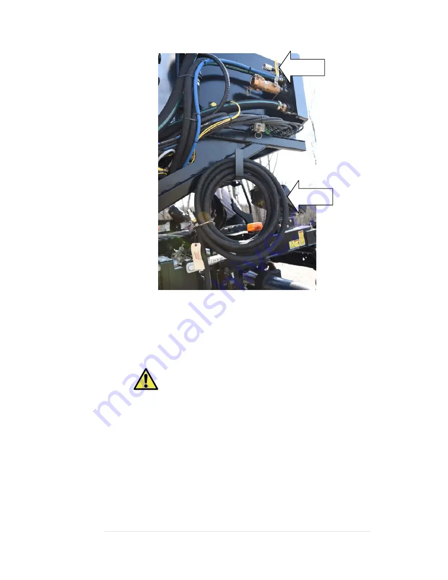
Figure 16:

 Spray wand connection and hose 

Emulsion lines 

Emulsion lines connect the emulsion tank(s) to the pumping station and 
the pumping the station to the spray bars.  

Warning:

 Only use factory‐supplied emulsion lines, 

emulsion line connections and hose clamps. Other hoses may 
rupture due to heat and cause serious injury. In most cases, a 
specific type of hose barb fitting is used to prevent the hose from 
disconnecting from the fitting. Do not use a standard worm‐gear 
hose clamp, which will not meet requirements.


Summary of Contents for Spray Paver

Page 1: ...09 16 2016 Rev F www integraldx com Spray Paver Operator s Manual Operation Maintenance Troubleshooting 2016 Integral dx All rights reserved...

Page 2: ...description 17 General specifications 19 Components 20 Emulsion tank group 20 Pump group 23 Emulsion spray group 24 Hydraulic system 36 Pneumatic system 39 Emulsion tank heating system 42 Control sys...

Page 3: ...ing the spray wand 92 Cleaning the machine 92 Cleaning the strainer screen in the pumping station 93 Checking the hydraulic oil level 93 Inspecting hydraulic hoses and emulsion hoses 93 Checking the f...

Page 4: ...hooting 106 Cleaning the emulsion tank 112 Cleaning a stuck pump 116 Setting the small emulsion pump bypass pressure 119 Appendices 120 Appendix 1 Valve and emulsion pump configurations for the pump f...

Page 5: ...urations of specific models may vary Limited warranty Integral dx warrants products of its manufacture when used correctly under normal operating conditions to be free of defects in materials and work...

Page 6: ...ies by or related to Buyer s use of Integral dx products Product Improvement Liability Disclaimer Integral dx reserves the right to make any changes in or improvements to its products without incurrin...

Page 7: ...r persons You must also ensure that the product will not be damaged or made unsafe by the procedure that you use Safety alerts Safety alert symbols in this manual or on the machine indicate important...

Page 8: ...les are included in this section of the manual Specific safety rules appear throughout the manual Danger Before operating or servicing this equipment complete proper training Also read and fully under...

Page 9: ...inch a hand foot etc Take care to not get body parts trapped between the parts An electrical hazard exists that could potentially provide a serious shock Avoid the hazard during operation Hot pipes ar...

Page 10: ...15 P a g e Figure 1 Safety decal location may vary depending upon model x2 x2 X2...

Page 11: ...r without the spray paving system operating The spray paver can operate with or without the paver operating The spray paver s emulsion pump s are capable of handling products ranging from light applic...

Page 12: ...t hopper do not tilt the hopper Attempting to tilt the hopper will damage the tanks and or paver Emulsion tank s The emulsion tank is an insulated vessel that holds the hot emulsion for spraying One t...

Page 13: ...pumping station Figure 5 Figure 5 Emulsion pumping station right side view The pump group controls the six basic pump functions Tank load Tank circulate Spray bar circulate Spray auto Spray bar vacuu...

Page 14: ...the paver hopper and replaces the paver s original push bar Tip Cover the front spray bar housing with a thin rubber mat to help with spillage cleanup and prevent damage to the spray bar hoses cylind...

Page 15: ...on or off The outer three spray nozzles are turned on or off individually The inner nozzles are turned on or off with other nozzles on the telescoping spray bar in gangs Avoid damage If the telescopi...

Page 16: ...erature and type Heavier emulsions require a higher nozzle height than lighter material to achieve a double overlap 1 Adjust the height of the center and telescoping spray bars using method 1 and or m...

Page 17: ...to the spray bars Warning Only use factory supplied emulsion lines emulsion line connections and hose clamps Other hoses may rupture due to heat and cause serious injury In most cases a specific type...

Page 18: ...er extension allows for correct depth of dumping into the paver minimizing spillage Figure 17 Asphalt hopper extensions Hydraulic system The hydraulic system is pressurized by a piston pump The pump p...

Page 19: ...oler Figure 19 supplies hydraulic oil to the pump as well as cools and filters the hydraulic oil Warning The oil cooler fan is thermostatically controlled It may startup at any time even if the paver...

Page 20: ...control the various valves Some models have an auxiliary connection at the compressor for a compressed air supply Air compressor The air compressor is located on the paver or screed deck It provides c...

Page 21: ...turn on or off the spray nozzles individuals or gangs on the front spray bars and ball valves that turn on off the rear spray bars Emulsion tank valves one valve on each tank for drawing emulsion and...

Page 22: ...41 P a g e Figure 21 Solenoid valve manifold in its enclosure...

Page 23: ...nclude heating elements Other tanks may or may not have heating elements depending upon the options chosen The heating elements are controlled by a thermostat with temperature sensor see Figure 22 Tip...

Page 24: ...nal power is not available remove emulsion from the tank for the overnight Note that clean out or release agent rinse is advised when emulsion is removed Warning Never plug the emulsion tank into exte...

Page 25: ...er let the emulation get above 200 F Boiling will occur if the temperature is too high and potentially cause burn injuries Also the water base will evaporate changing the properties of the emulsion On...

Page 26: ...elements unless they are fully submerged The emulsion tank low level switch Figure 24 is attached to the tank level indicator It shuts off the heating elements when the emulsion in the tank is low eno...

Page 27: ...turns off tank heat in case of thermostat failure To adjust the switch loosen the ring turn the dial to the desired temperature setting and tighten the ring Avoid Damage Always set the emulsion tank o...

Page 28: ...ts are used by the control system to set emulsion flow rate Application rate in gal yd2 or L m2 Set by the operator Spray bar width Calculated from operator s spray nozzle selection Vehicle speed Dete...

Page 29: ...display screen unit see page 58 for specific operation Operate pump functions Extend retract the left and right telescoping spray bars tilt the front spray bar housing lock the front spray bar housin...

Page 30: ...rves as the power switch for turning on off the spray paving system and also is the emergency stop button Pull it up to power on Press it down to disable power The green on and red off buttons are the...

Page 31: ...ote Settings last used when powered down are retained and activated during startup Note Keys may change function depending upon the screen Figure 31 shows the key naming 1L 5L and 1R 5R that will be u...

Page 32: ...forward and backward through the display screens Sprayer Selection Pump Function Totals Camera1 Camera2 Password Note Keys 1L and 2L are dedicated arrows are always present except on the camera screen...

Page 33: ...right telescoping spray bars Each of the telescoping spray bars has a group of switches that control an individual nozzle the outer nozzles and a group of switches that control a gang of nozzles the i...

Page 34: ...itch or an entire spray bar A switch is blackened when it is deselected Tip To select combinations of spray bar sections push the up arrow on the multi navigation key The selections are highlighted wi...

Page 35: ...ion rate and is in gal yd2 or L m2 With all other pump functions the rate is a percentage of full pump capability Tilting the front spray bar housing Press and hold key 3L to tilt the front spray bar...

Page 36: ...vigation key 5R to select spray bars left and right front center or left and right rear They will highlight in green 2 Press the Pump key 4R to activate the Spray Bar Vacuum pump function Warning pump...

Page 37: ...rface page 82 5 Vacuum the spray bars Pulls emulsion back in the tank when spraying is complete page 84 6 Clean out and rinse the spray bars Cleans the system after use to prevent clogging page 85 Loa...

Page 38: ...hazard Clean up spilled emulsion before operating the machine A spark could ignite the spillage Danger Do not smoke while loading the machine Do not load the machine near open flame or sparks Death or...

Page 39: ...s 1 Use the Sprayer Selection screen to extend the telescoping spray bars to the screed width tilt the front spray bar down and select spray nozzles 2 Select Pump Function Spray Auto and activate the...

Page 40: ...5 5 bar which is about five times the typical spraying pressure Using the spray wand 1 Select Pump Function Spray Auto and activate the pump 2 Use an arc spraying motion to coat the surface until the...

Page 41: ...0 IDX11170 HOSE 1 SUCTION 16 GMV to spraybars 10 IDX10968 HOSE 2 SUCTION 32 GMV to tanks 10 IDX10965 COUPLING PIPE 0 75 NPT BLK IRON 2 IDX11502 COUPLING PIPE 1 NPT BLK IRON 2 IDX10158 COUPLING PIPE 1...

Page 42: ...el in the clean out tank 94 X Clean blockage from the emulsion tank overflow tubes 94 X Clean the hydraulic cylinder rods 94 X Check the oil in the air compressor 94 X Drain the air compressor tank an...

Page 43: ...ing Wear protective glasses and other required safety equipment when servicing or repairing the machine Warning Follow good shop practices Keep service area clean and dry Be sure electrical outlets an...

Page 44: ...be sure all lines fittings and couplers are tight and in good condition Leaking fittings are a fire hazard Hydraulic fluid under pressure can pierce skin resulting in serious injury or toxic reaction...

Page 45: ...pumping station Checking the hydraulic oil level 1 When hydraulic oil is cool the oil level should be visible at the bottom of the sight glass but no higher than halfway up the sight gauge 2 If addit...

Page 46: ...tomatic drain open the drain cock on the filter bowl to drain any water condensate If the system has an automated drain leave the drain cock open for the automated drain to work Inspecting the packing...

Page 47: ...the tanks to the paver hopper Make sure they are tight and secure Checking spray nozzle alignment 1 View the spray pattern to see if all nozzles spray at the same angle 2 Set nozzles as shown in Figur...

Page 48: ...key 2R see Figure 48 for at least 5 seconds Figure 48 Zeroing the job totals 4 Begin spraying in the Spay Auto mode Continue until the tank gets low Be sure to not run the tank too low or a dipstick m...

Page 49: ...the display screen unit enter the password The Service screen will appear 9 On the Service screen use up and down arrows 1R and 3R to select the Small Pump Calibration Factor 10 Use the keys correspo...

Page 50: ...he Tank Circulate pump function Adjust the pump flow rate to 100 4 Remove one of the emulsion tank covers and look into the emulsion tank to see if diesel fuel is circulating in the tank Add diesel fu...

Page 51: ...will be cleaning agent typically diesel fuel inside all spray bar pipes and in the emulsion tank s To ensure Tank Circulate and Spray Bar Circulate can be run without pulling air on the suction side...

Page 52: ...e pump function to circulate cleaning agent from the emulsion tank to the asphalt pumping station and then back to the emulsion tank Circulate for a minimum of 5 minutes at a high flow rate 2 Verify b...

Page 53: ...rate of 10 gpm With the master spray switch on the small asphalt pump speed is regulated to supply the application rate based on the vehicle speed and the selected spray width If the vehicle is not mo...

Page 54: ...Clean Out 1 Activate the Clean Out function Verify the small and large asphalt pump shafts are rotating 2 Verify valve actuator open closed positions using the diagram in Appendix 2 Pump group flow pa...

Page 55: ...ump station valves see Appendix 1 Nozzles mismatched Verify all nozzles are the same size and style Flow rate for nozzles too low Increase flow through nozzles by 1 increasing application rate and or...

Page 56: ...e to remove any flammable solvents from the area to prevent fires or explosions An infrared temperature gun is required to be sure that the pump is not heated above 212 F 100 C If the asphalt emulsion...

Page 57: ...e accurate This is a problem with the small emulsion pump which requires accurate flow for accurate control of the application rate Check and reset the small emulsion pump bypass pressure as follows 1...

Page 58: ...Integral dx 121 N 1st Street Montevideo MN 56265 USA T 320 269 3227 www integraldx com sales integraldx com...

Reviews: