11
Component Identification
No.
Module name
7
Hard disk backplane power supply interface
8
Hard disk backplane signal interface J91
9
Hard disk backplane signal interface J92
10
M.2 Riser slot
11
Right-hand front panel interface
12
PCH SD card slot
13
BMC SD card slot
14
CLR_CMOS
15
Motherboard handle 0
16
UID button
17
BMC debug interface
18
BMC management interface/USB3.0 slot x2
19
10G on-board network interface x2
20
VGA interface
21
TPM interface
22
KVM interface
23
MINISAS interface 0
24
MINISAS interface 1
25
MINISAS interface 2
26
MB PDB interface
For the position of the CMOS clear jumper, see 3.5 Motherboard Components.
Item
Function description
Jumper function
CLR_CMOS
CMOS clear jumper
Short-circuit pin1-2, normal status;
Short-circuit pin2-3, clear CMOS.
Note:
It is required to shut down the system, as well as disconnect the power supply during CMOS
clearing. Hold for 5 seconds after short-circuiting Pin2-3, and then short-circuit Pin1 and
Pin2 (the default status) of CLR_CMOS jumper with a jumper cap, to restore to its original
status.
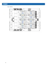
3.6 GPU components
The upper layer of the GPU module is GPU0-GPU7, and the lower layer is GPU8-GPU15, as
Summary of Contents for AGX-5
Page 1: ...Inspur Server User Manual NF5888M5 AGX 5 V1 1 ...
Page 18: ...12 shown below ...
Page 22: ...16 ...
Page 37: ...31 Cabling Note Please route the cables according to the purchased machine configuration ...
Page 46: ...40 Fig 2 11 Fig 2 12 Fig 2 13 ...
Page 113: ...BMC settings 107 ...
Page 116: ...110 ...
Page 118: ...112 One key collect log One key collect log ...
Page 123: ...BMC settings 117 ...
Page 139: ...BMC settings 133 ...
Page 142: ...136 ...
Page 144: ...138 ...
Page 149: ...BMC settings 143 ...


