Version 1.01
22
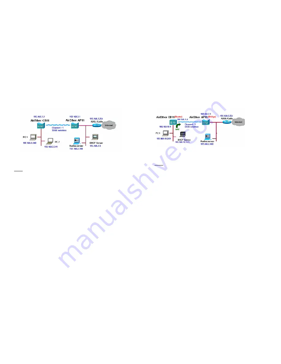
3.1 Wireless Client Bridge-to-Central Wireless
Bridge
Figure 3-2
Refer to Figure 3-2 for the following setup.
Note:
The AirEther AP11 is the Central Wireless Bridge and AirEther CB11
is the Wireless Client Bridge
Step 1
Set the AirEther AP11 to perform a bridge (
bridge IP address:
192.168.2.1
).
Step 2
Set Wireless parameters on the AP11 to:
Channel (1)
and
SSID
(wireless)
Step 3
Set the AirEther CB11 to function in the bridge mode (
bridge IP
address: 192.168.2.2
).
Step 4
Set Wireless parameters on the CB11 to:
Channel (1)
and
SSID
(wireless)
, and these parameters must be the same with COU.
Step 5
Left side subnet is transparent to the right side.
Step 6
DHCP server assign IP address to PC1 and PC2
Version 1.01
23
3.2 Wireless Client Router-to-Central Wireless
Bridge
Figure 3-3
Refer to Figure 3-3 for the following setup.
Note:
The AirEther AP11 is the Central Wireless Bridge and AirEther CB11
is the Wireless Client Bridge
.
Step 1
Set the AirEther AP11 to function in the bridge mode (
bridge IP
address: 192.168.2.1
).
Step 2
Set Wireless parameters on AirEther AP11
Channel (1)
and
SSID
(wireless)
.
Step 3
Set the AirEther CB11 to function as a Router (
Wireless Interface
IP: 192.168.2.2, Ethernet Interface IP: 192.168.10.1)
. Enable
NAT on Wireless Interface (
default route is 192.168.2.254
).
Step 4
Set Wireless parameters on the AirEther CB11:
SSID (wireless),
same
parameters as the AP11.
Step 5 T
he DHCP server assigns IP address to PC1
Summary of Contents for AirEther CB11
Page 29: ...Version 1 01 54 ...


