Page 20 of 44
EP20-XXXXX-XXX-XXX (en)
7. ELECTRICAL INSTALLATION FOR HAZARDOUS LOCATIONS
7.1. General Wiring
Before commissioning verify that the information shown on
the nameplate is compatible with explosive atmosphere that
is present and with the zone where used.
All electrical wiring must be done by qualified, experienced,
and certified electrician and comply with all local and nation-
al electrical codes. For NEC / CEC applications (North Ameri-
ca), ensure wiring is done according to NFPA 70 / CSA C22.1.
For ATEX / IECEx applications, ensure wiring is done accord-
ing to IEC / EN 60079-14.
System designer, installer, and maintenance personnel are re-
sponsible to ensure proper wiring and grounding (earth) and
protection from lightning according to IEC 62305-3:2010.
Ensure that the VFD and motor are properly de-energized
prior to any maintenance and that proper lock out / tag out
procedures are followed. Refer to the VFD nameplate for the
required amount of time to fully discharge capacitors.
Maintenance should not be completed in the presence of an
explosive gas or dust atmosphere.
Cable glands and plugs shall be selected in accordance with
IEC 60079-0 and EPL Gb/Db at the minimum. They must be
correctly sized, tightened, and gripped and account for any
coldflow characteristics of the cables. Furthermore, these
components must maintain and ensure the mode of protec-
tion (Ex) and the rated index of protection (IP).
The hazardous motors are equipped with 3 PTC thermal sen-
sors (1 per phase). It is required that these are properly wired
to the PTC thermistor card in the VFD to de-energize the mo-
tor in the event of a thermal event. The PTC thermal sensors
have a set point of 150°C on the motor windings to ensure
rated surface temperatures.
Ensure the hazardous motor is painted red to indicate haz-
ardous duty model.
Ensure the VFD is placed in a safe (non-hazardous) area.
7.2. Power Wiring
Refer to section 6.1 for VFD - Wiring Diaphragm.
Refer to section 6.3 for VFD Input Power Requirements.
Refer to section 6.4.1 for VFD - Input Power Wiring.
Refer to section 6.4.2 for VFD - Output Power Wiring.
Refer to section 6.4.3 for Motor - Input Power Wiring.
* See page 4 for hazardous motor terminal box gland type and sizes.
* Ensure the use of a shielded power cable between the VFD and the motor.
7.3. Control Wiring (Required)
7.3.1 Leak Detector Wiring
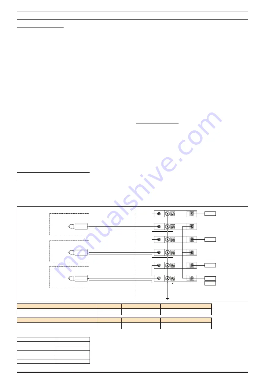
There are 3 leak detectors that are used per pump which come with 2 meters of cable length with flying lead connections.
Each leak detector requires the use of 2 zener barriers (not supplied with pump but available as an accessory item) which
should be wired as shown by the schematic below by a qualified, experienced and certified electrician according to any local
and national electric codes. See below for leak detector safe loop calculations.
HAZARDOUS AREA
SAFE AREA
Pin 18 on VFD
(Digital input)
Pin 19 on VFD
(Digital input)
Pin 32 on VFD
(Digital input)
Pin 13 on VFD
(24V DC)
Pin 20 on VFD
(Common)
White
Red
Black
White
Red
Black
White
Red
Black
Leak Detect Diaphragm 1
Leak Detect Diaphragm 2
Leak Detect Diaphragm 3
ZENER Barrier, Leak Detection Sensor PN
Voltage
Device Rating (mA)
Temperature Rating
97414 (ATEX / IECEx / NEC / CEC)
24 VDC
100
-4
°
F - 140
°
F (-20
°
C - 60
°
C)
Leak Detection Sensor PN
Voltage
Device Rating (mA)
Temperature Rating
96270-2 (ATEX / IECEx / NEC / CEC)
24 VDC
40
-0
°
F - 176
°
F (-18
°
C - 80
°
C)
Recommended cable (3
Conductor with Single Outer Jacket)
Manufacturer
Alpha Wire
Part Number
1173C
Conductor
22 AWG
Voltage Rating
300 V RMS
C
33 PF/FT @ 1KHz
L
0.18 mH/Ft


