Infinova V6812IR-H0 Series User Manual Download Page 12

41 


4-2 

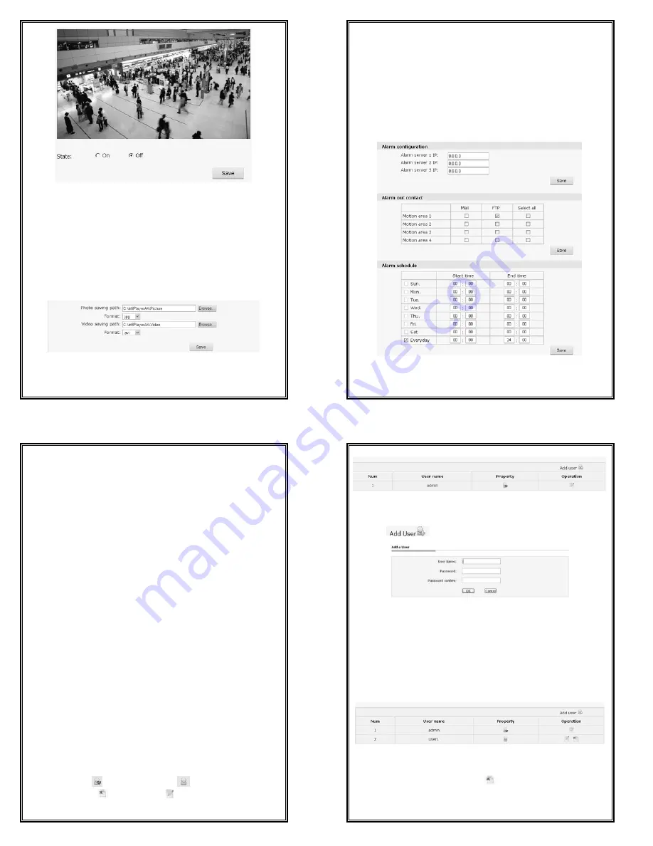
Active video tampering settings


You can open or close this function on this page. When the function is open and 

active video tampering is detected, the alarm lamp on the top of the page turns 

red. 


4.5.7 Storage Path   

You can set the photo saving path and recording saving path in the following 
interface. 


Figure 4-29 Storage Path 

Default photo saving path: 

C:\InfiPlayerAX\Picture.  

42 

Default video saving path: 

C:\InfiPlayerAX\ Video.   

Photo and video formats can also be set. The default photo format is 

.jpg and the 

default video 

format 

is .avi. 


To change the saving path, click the button “Browse” and select the path from 
the popup dialog box.   
 

4.6 Alarm Settings 

Click “Alarm” in the navigation bar to display the following Alarm Settings 
interface: 


Figure 4-30 Alarm Settings 


43 

Alarm configuration 

Alarm Server IP: used to set the IP address of alarm server. If alarm occurs, it 
will inform the alarm server. 


Alarm out contact 

Users can set the relevant alarm response way for motion detection alarm. 
Options: Mail, FTP. After setting completed, click “Save” button to take effect. 
Note: when “FTP” or “Mail” is selected, you need to set FTP or SMTP 
parameters in Network Settings, refer to Section 4.3.2 or Section 4.3.3 for 
details. 
 

Alarm schedule 

V6812IR-H0 series camera can set the effective alarm schedule. Select the 
alarm period (if Sunday is selected, alarm will be enabled during the set period 
of each Sunday; if Everyday is selected, alarm will be enabled during the set 
period of everyday), and then, set the time period. Enter the start time and end 
time in the 24-hour format. The end time must be larger than the start time.   
 

4.7 Account Settings 

The default super user is admin (password: admin). Super user can add, delete 
common user, and change the password of common users. Super user can 
change his password. Do change Super user’s password in time to secure your 
system. 
A maximum of 7 common users are supported. 
Detailed instruction about how to add and delete user are addressed below. 
Click the Account option tab in the Settings interface, the following account 
information will display. The “Num” item shows the current user number. In 
“Property” column, 

  stands for super user; 

  stands for common user. In 

“Operation” column, 

means to delete;   means to edit user information. 

See figure below: 

44 


Figure 4-31 Account Settings 

1. Add Users 

(1)


Click “

”, enter the interface of “Add a User”.


Figure 4-32 Add a User 

(2) Enter the desired User Name and Password (Note: User name and password 
shall include letter, number and underline only. No special character is allowed. 
The string length of user name is legal between 1 and 30 characters and that of 
password is between 5 and 20 characters.) 
 
(3) Click “OK” button. If the setting is successful, the new user name will 
appear in the account list. Take new user “user1” as an example:


Figure 4-33 

2. Delete Users


In the “Account setting” interface, click 

  button of the “Operation” item to 

delete user. The following dialog box will display:


Summary of Contents for V6812IR-H0 Series

Page 1: ...while there is no guarantee that interference will not occur in a certain particular installation situation Read this manual carefully before installation This manual should be saved for future use Important Safety Instructions and Warnings Electronic devices must be kept away from water fire or high magnetic radiation Clean with a dry cloth Provide adequate ventilation Unplug the power supply whe...

Page 2: ...ng 1 3 System Requirement Configuration of the computer to display image and control the camera CPU Intel Pentium 4 2 4 GHz or above RAM 512 MB or greater Network Port 100M Ethernet port Operating System Microsoft Windows 7 Microsoft Windows XP IE Browser Version Microsoft Internet Explorer 6 0 or above 3 1 4 Product Model This manual is for the following models V6812IR H0165SA HD Megapixel IR IP ...

Page 3: ...g the unit and contact your local dealer 7 This camera features AGC circuit so when the camera is applied under low illumination sensitivity will enhance automatically making images look rough which is normal 8 The camera power supply is 12VDC Be sure of the terminal correct 9 Firstly perform network settings after login Gateway IP address should be set to the IP address of the gateway that the de...

Page 4: ... is 192 168 1 254 For normal access correctly set local IP parameters before system login Do log in the system with the default super user for the first time to run the software The default Super User is admin password admin Note Do change the password in time to secure your system 2 Install and run Control After a successful login the prompt of security warning will pop up to remind the user to i...

Page 5: ... supports local recording Click the recording button to start recording when the button changes to click it to stop recording During local recording REC appears on the video screen Click the button 15 to enter the recording storage path Default C InfiPlayerAX Video Users can set the snap shooting and recording storage path in the video settings interface Indicate that the motion detection and priv...

Page 6: ...e process Power off will make update fail even damage the original program or unable to update again After update successfully it needs to reboot the system There is time prompt in the web page during reboot After reboot it will skip to new web page to run new program Note Available only for the super user Factory Settings V6812IR H0 series camera provides online reset function which greatly facil...

Page 7: ...ngs then alarm triggered images FTP upload can be achieved 4 3 3 SMTP Settings Figure 4 11 SMTP Settings 23 User needs to set mail server recipient etc in SMTP settings interface Server IP Set mail server address From Set sender s mail address To Mail address of recipient CC Mail address of the person copy to Authentication Enable or disable authentication function This function should be set acco...

Page 8: ...ck Camera in the navigation bar to enter the interface shown as below Figure 4 17 Basic Settings 4 4 1 Basic Settings You can set the following parameters Flicker frequency 50Hz or 60Hz CVBS it automatically changes with the flicker frequency Enable or disable backlight compensation or digital WDR Exposure set scene AGC auto aperture shutter speed and manual AGC can also be set in this interface E...

Page 9: ...ue gain 31 4 4 4 IR Settings Figure 4 21 IR mode set IR illuminators working mode Options Day Night Auto turn on or off as per ambient light Switch time in auto mode the response time for day night switch Power set the adjusting mode of illuminators power consumption Options Auto Manual In auto mode adjust illuminators brightness as per ambient light In manual mode adjust the brightness by moving ...

Page 10: ...pies less bandwidth When the setting goes with constant bit rate then the image is transmitted under a constant bandwidth 34 Bit Rate You have to set the upper limit of bit rate if vbr is selected the stream size will be fixed if cbr is selected and the stream size is defined in the Bit Rate For major stream the bit rate can be 256 10000kbps for minor stream the bit rate can be 256 2000Kbps Image ...

Page 11: ...nction If there is certain location within the surveillance area where operators are not allowed to see and thus Privacy Mask can be applied System covers and shields the sensitive area via Privacy Mask setting to avoid operators observing certain sensitive locations on monitor Note do turn on privacy mask function in Live View interface before privacy mask setting Figure 4 25 Privacy Mask Setting...

Page 12: ...ing the set period of each Sunday if Everyday is selected alarm will be enabled during the set period of everyday and then set the time period Enter the start time and end time in the 24 hour format The end time must be larger than the start time 4 7 Account Settings The default super user is admin password admin Super user can add delete common user and change the password of common users Super u...

Page 13: ... rounds or more Make sure the filter can be well closed Step 3 Close the magnetic ring filter Notice The magnetic ring filter should be installed no more than 50 mm away from the power output connector As shown in Figure 3 the cable length from A to B should be 50mm at most Figure 1 Closed magnetic ring filter Figure 2 Open magnetic ring filter Figure 3 Power cable with magnetic ring filter 48 APP...

Page 14: ...burial thus to ensure the electric connection to the metal tube In case it s difficult to thread the cable through the tube all the way it s acceptable to use tube threaded cables only at both ends of the transmission line yet the length in burial should be no less than 15 meters The cable sheath and the tube should be connected to the lightning proof grounding device Additional high power lightni...

Reviews: