


Data Sheet
116
Rev. 1.00
2017-07-31
TLE9262BQXV33
Supervision Functions
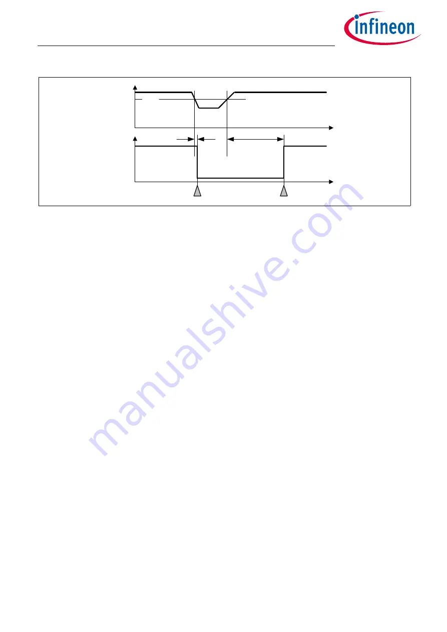
Figure 52 VCC1 Undervoltage Timing Diagram
An additional safety mechanism is implemented to avoid repetitive VCC1 undervoltage resets due to high
dynamic loads on VCC1:
•
A counter is increased for every consecutive VCC1 undervoltage event (regardless on the selected reset
threshold),
•
The counter is active in SBC Init-, Normal-, and Stop Mode,
•
For VS <
V
S,UV
the counter will be stopped in SBC Normal Mode (i.e. the VS UV comparator is always enabled
in SBC Normal Mode),
• A 4th consecutive VCC1 undervoltage event will lead to SBC Fail-Safe Mode entry and to setting the bit
VCC1_UV _FS
•
This counter is cleared:
– when SBC Fail-Safe Mode is entered,
– when the bit
VCC1_UV
is cleared,
– when a Soft Reset is triggered.
Note:
It is recommended to clear the VCC1_UV bit once it was set and detected.
15.6.2
VCC1 Overvoltage
For fail-safe reasons a configurable VCC1 overvoltage detection feature is implemented for SBC Init- and
Normal Mode.
In case the
V
CC1,OV,r
threshold is crossed, the SBC triggers following measures depending on the configuration:
•
The bit
VCC1_ OV
is always set;
• If the bit
VCC1_OV_RST
is set and
CFGP
= ‘1’, then SBC Restart Mode is entered. The FOx outputs are
activated. After the reset delay time (
t
RD1
), the SBC Restart Mode is left and SBC Normal Mode is resumed
even if the VCC1 overvoltage event is still present (see also
Figure 53
). The
VCC1_OV_RST
bit is cleared
automatically;
• If the bit
VCC1_OV_RST
is set and
CFGP
= ‘0’, then SBC Fail-Safe Mode is entered and FOx outputs are
activated.
Note:
Before entering SBC Stop Mode the bit
VCC1_OV_RST
must be set to ‘0’ to avoid unintentional SBC
Restart or Fail-Safe Mode entry. The status bit
VCC1_ OV
could be set unintentionally. The reason is
RO
t
VCC1
V
RTx
t
RD1
SBC Normal
t
t
RF
SBC Restart
SBC Normal