


150
TR
SI
CZ
HU
RO
PL
RU
UA
SK
ES
IE
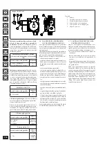
2.5 USING THE BOILER.
Before ignition, make sure the heating system
is filled with water and that the manometer (7)
indicates a pressure of 1 ÷ 1.2 bar.
- Open the gas cock upstream from the boiler.
- Press the button (2) until the display switches
on, after which press the button in sequence
(2) and take the boiler to the summer (
)
or winter (
) position.
•
Summer
(
)
:
in this mode the boiler func-
tions only to produce the DHW, the tempera-
ture is set via the buttons (3-4) and the relative
temperature is shown on the display via the
indicator (16).
• Winter
(
)
:
in this mode the boiler functions
both for producing domestic hot water and
heating the environment. The temperature of
the DHW is always regulated via buttons (3-4),
the heating temperature is regulated via buttons
(5-6) and the relative temperature is shown on
the display via the indicator (16).
From this moment the boiler functions auto-
matically. With no demand for heat (heating
or domestic hot water production) the boiler
goes to “standby” function, equivalent to the
boiler being powered without presence of flame.
Each time the burner ignites, the relative flame
present symbol is displayed (10) with relative
power scale.
•
Operation with Comando Amico Remoto
remote control
V2
(CAR
V2
) (Optional)
. If the
CAR
V2
is connected, the (
) symbol will
appear on the display. The boiler regulation pa-
rameters can be set via the CAR
V2
control panel
and the reset button (1) remains active on the
boiler control panel, along with the switch-off
button (2) (“off” mode only) and the display
where the functioning state is shown.
Important:
if the boiler is put into “off” mode
on the CAR
V2
the “CON” connection error
symbol will appear on the CAR. The CAR
V2
is
however powered constantly so as not to loose
memorised programs.
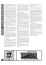
•
Functioning with optional external probe
(
)
.
In the case of a system with optional
external probe, the boiler flow temperature for
room central heating is managed by the exter-
nal probe depending on the external tempera-
ture measured (Par. 1.6). The flow temperature
can be modified by selecting the functioning
curve via buttons (5 and 6), selecting a value
from “0 to 9” (Fig. 1-8).
With external probe present, the relative
symbol will appear on the display (12). In the
central heating phase, if the temperature of the
water contained in the system is sufficient to
heat the radiators, the boiler can only function
with the activation of the pump.
•
“Stand-by” mode.
Press button (2) in suc-
cession until the (
) symbol appears. The
boiler remains active from this moment and the
anti-freeze function, pump anti-block function
and 3-way and signalling of any anomalies is
guaranteed.
N.B.:
in these conditions the boiler is consid-
ered still live.
•
“Off” mode.
By holding the button (2) down
for 8 seconds, the display switches-off and the
boiler is off completely. The safety functions are
not guaranteed in this mode.
N.B.:
in these conditions the boiler is consid-
ered still live even if there are no functions
active.
•
Display functioning.
The display lights up dur-
ing the use of the control panel, after 15 seconds
inactivity, the brightness drops until just the
active symbols are displayed. The lighting mode
can be varied via parameter P2 in the circuit
board customisation menu.
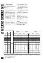
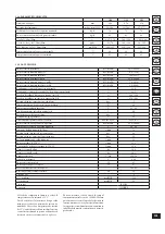
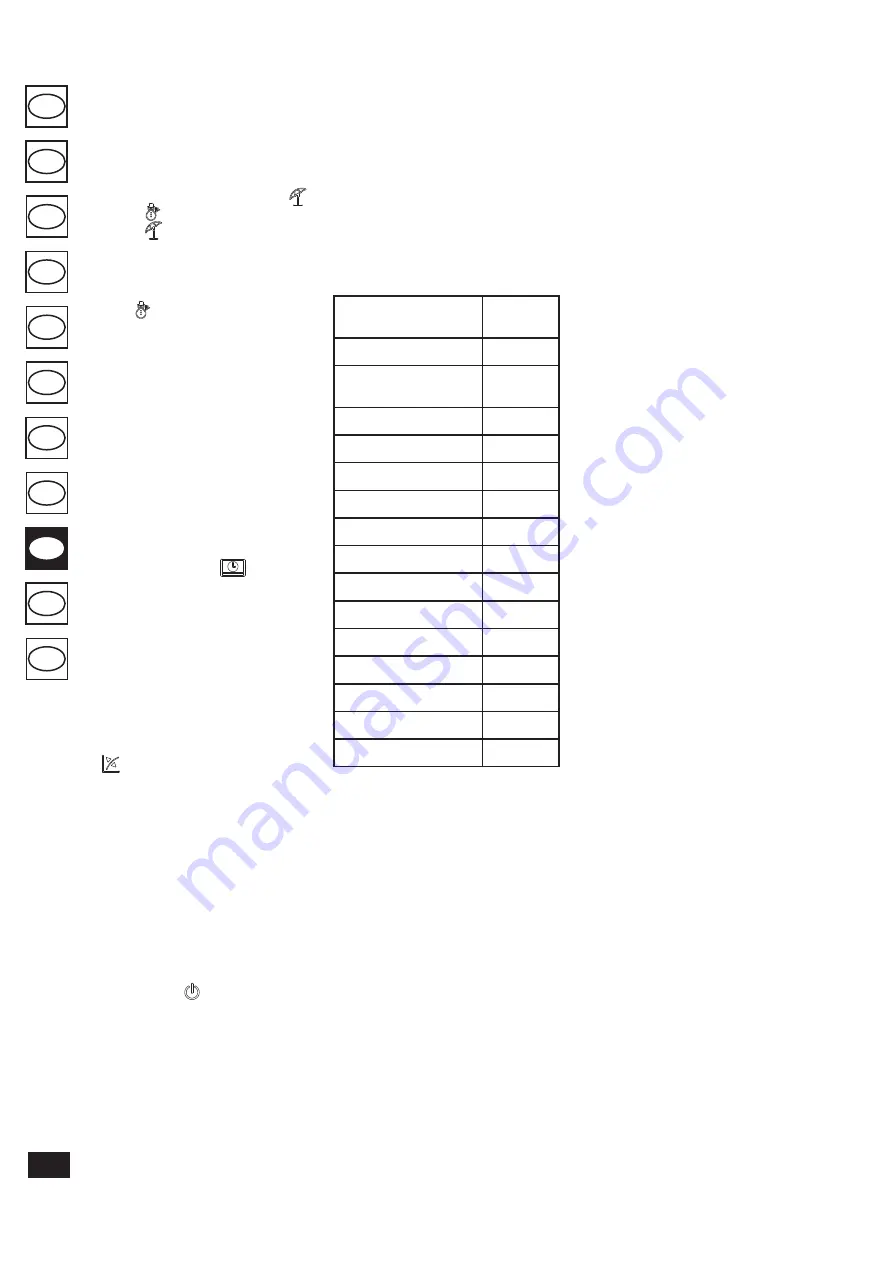
2.6 TROUBLESHOOTING.
The boiler signals out anomalies by flashing on
the display and relative error codes, listed on the
table, are displayed.
Anomaly signalled
Code
displayed
(flashing)
No ignition block
01
Safety thermostat block (over-
temperature), flame control
anomaly
02
Flue safety thermostat
anomaly
03
Flow probe anomaly
05
Domestic hot water probe
anomaly
06
Maximum N° of reset
08
Insufficient system pressure
10
Configuration error
15
Parasite flame
20
Push button control panel
anomaly
24
Insufficient circulation
27
Loss of remote control com-
munication.
31
Low power supply voltage
37
Loss of flame signal
38
Block due to loss of continu-
ous flame signal
43
Ignition block.
The boiler ignites automati-
cally with each demand for room heating or hot
water production. If this does not occur within
10 seconds, the boiler goes into ignition block
(code 01). To eliminate “ignition block” the Reset
button (1) must be pressed. On commissioning
or after extended inactivity it may be necessary
to eliminate the “ignition block”. If this phe-
nomenon occurs frequently, contact a qualified
technician for assistance (e.g. Immergas After-
Sales Technical Assistance Service).
Overtemperature thermostat block.
During
normal functioning, if a fault causes excessive
overheating internally, the boiler goes into over-
temperature block (code 02). After allowing to
cool, eliminate the “overtemperature block” by
pressing the Reset key (1). If this phenomenon
occurs frequently, contact a qualified technician
for assistance (e.g. Immergas After-Sales Techni-
cal Assistance Service).
Flue safety thermostat anomaly.
This occurs if
the flue gas evacuation pipe does not function
correctly (code 03). The boiler goes into stand-by
for 30 minutes, after which, if normal working
conditions are restored, it re-starts without hav-
ing to be reset. In the case of 3 consecutive blocks,
the boiler itself blocks and it must be reset in
order to re-start. However, it is indispensable to
call a qualified technician (e.g. Immergas After-
Sales Technical Assistance Service) in order to
solve the problem.
Delivery probe anomaly.
If the board detects
an anomaly on the delivery probe (code 05), the
boiler will not start; contact a qualified technician
for assistance (e.g. Immergas After-Sales Techni-
cal Assistance Service).
Domestic hot water probe anomaly.
If the board
detects an anomaly on the domestic hot water
NTC probe, the boiler signals the anomaly. In this
case the boiler continues to produce domestic hot
water but not with optimal performance. Moreo-
ver, the DHW anti-freeze function is prevented
and an authorised technician must be called (e.g.
Immergas After-Sales Service).
Maximum N° of reset.
To eliminate any
“anomaly” the Reset button (1) must be pressed.
The Anomaly can be reset 5 times consecutively,
after which the function in inhibited for at least
one hour. One attempt is gained every hour for
a maximum of 5 attempts.
Insufficient system pressure.
Water pressure
inside the heating system (code 10), sufficient to
guarantee the correct functioning of the boiler,
is not detected. Check that the system pressure
is between 1÷1.2 bar.
Configuration error.
If the board detects an
anomaly or incongruence on the electric wiring,
the boiler will not start. If normal conditions are
restored the boiler restarts without having to be
reset. If this anomaly persists, contact a qualified
technician for assistance (e.g. Immergas After-
Sales Technical Assistance Service).
Parasite flame.
This occurs in case of a leak on
the detection circuit or anomaly in the flame
control unit (code 20), try to reset the boiler.
If the anomaly continues contact a qualified
technician (e.g. Immergas After-Sales Technical
Assistance Service).
Push button control panel anomaly.
This occurs
when the circuit board detects an anomaly on the
push button control panel. If normal conditions
are restored the boiler restarts without having
to be reset. If this anomaly persists, contact a
qualified technician for assistance (e.g. Immergas
After-Sales Technical Assistance Service).
Insufficient circulation
This occurs if there is
overheating in the boiler due to insufficient water
circulating in the primary circuit (code 27); the
causes can be:
- low system circulation; check that no shut-off
devices are closed on the heating circuit and
that the system is free of air (deaerated);
- circulating pump blocked; free the circulating
pump.
If this phenomenon occurs frequently, contact a
qualified technician for assistance (e.g. Immergas
After-Sales Technical Assistance Service).
Summary of Contents for MINI NIKE 24 3 E
Page 2: ......
Page 21: ...19 PL ES TR SI CZ HU RO IE RU UA SK Fig 3 5 4 4 5 6 6 d d c ...
Page 39: ...37 TR SI CZ HU RO IE RU UA SK ES PL Rys 3 5 4 4 5 6 6 d d c ...
Page 56: ...54 PL SI CZ HU RO IE RU UA SK ES TR Şek 3 5 4 4 5 6 6 d d c ...
Page 73: ...71 TR SI PL HU RO IE RU UA SK ES CZ Obr 3 5 4 4 5 6 6 d d c ...
Page 90: ...88 TR PL CZ HU RO IE RU UA SK ES SI Sl 3 5 4 4 5 6 6 d d c ...
Page 107: ...105 TR SI CZ PL RO IE RU UA SK ES HU 3 5 ábr 4 4 5 6 6 d d c ...
Page 124: ...122 TR SI CZ HU RO IE PL UA SK ES RU Илл 3 5 4 4 5 6 6 d d c ...
Page 141: ...139 TR SI CZ HU PL IE RU UA SK ES RO Fig 3 5 4 4 5 6 6 d d c ...
Page 160: ...158 TR SI CZ HU RO PL RU UA SK ES IE Fig 3 5 4 4 5 6 6 d d c ...
Page 177: ...175 TR SI CZ HU RO IE RU UA PL ES SK Obr 3 5 4 4 5 6 6 d d c ...
Page 194: ...192 TR SI CZ HU RO IE RU PL SK ES UA Мал 3 5 4 4 5 6 6 d d c ...
Page 197: ......


