background image

43

Instructions for the installer

ADJUSTING SCREW 

MAXIMUM POWER

ADJUSTING SCREW 

MINIMUM POWER

Follow this procedure to adjust the other modules 

as well.

If the measured flow rate is too low, make sure the supply and draining 

systems (the supply and draining pipes) are not obstructed.

If they are not obstructed, make sure the burner and/or exchanger 

are not dirty.

C) Completing basic calibration.

- Check CO

2

 values at the minimum and maximum flow rate.

- Touch up if necessary.

For smooth operation, calibrate the CO

2

 values taking 

care to observe the values in the table.

- Close the cap for the flue inspection point back up.

NOTE: do not force the adjusting screw limit switch 

limits.

A) Adjustment at maximum power.

- Unscrew the closing cap for flue exhaust analysis point.
- Place the analyser probe inside the flue analysis point.
- Make burner 1 operate at max power, following the procedure 

illustrated below in "chimney sweep function " (100 % CASC 

MANUAL).

- Make sure that the CO

2

 level falls within the values indicated in the 

"Nozzle pressure" table.

- Possibly correct the value by turning adjusting screw 

"A"

 CLOCKWISE 

to decrease it and COUNTER-CLOCKWISE to increase it.

B) Adjustment at minimum power.

- Make burner 1 operate at min power, following the procedure 

illustrated below in "chimney sweep function " (10 % CASC 

MANUAL).

- Make sure that the CO2 level falls within the values indicated in the 

"Nozzle pressure" table. 

- Possibly correct the value by turning adjusting screw 

"B"

 CLOCKWISE 

to increase it and COUNTER-CLOCKWISE to decrease it.

Summary of Contents for ARES 440 TEC ERP

Page 1: ...1 039293ENG ARES 440 TEC ERP ARES 550 TEC ERP ARES 660 TEC ERP ARES 770 TEC ERP ARES 900 TEC ERP Modular condensing boiler IE Instructions and warnings Installer Maintenance technician...

Page 2: ......

Page 3: ...alves 22 3 13 complete optional kits 23 3 14 condensate drain 24 3 15 Connecting the flue 25 3 16 Flue exhaust manifold connection 25 3 17 Electrical connections 27 General recommendations 27 230V ele...

Page 4: ...er of the importance of aeration vents and the flue exhaust system highlighting how essential they are and how it is strictly forbidden to change them Inform the user on how to control the water press...

Page 5: ...ched fittings use suitable wrenches only Improper use and or unsuitable tools can cause damage for ex water and gas leaks ATTENTION Instructions for appliances running on propane gas Make sure that th...

Page 6: ...horoughly in any case using products that are suitable for the entire system and install a Y strainer with two cut off valves on the return pipe to the boiler so that it can be cleaned as needed This...

Page 7: ...attacks To minimise corrosion it is essential to use a corrosion inhibitor In order for it to work efficiently however the metal surfaces must be clean The best inhibitors on the market also contain...

Page 8: ...e terminals In case of breakdown and or poor operation of the appliance switch it off and do not attempt in any way to repair it or intervene directly Only contact an authorised company that has been...

Page 9: ...Possibility of controlling the power of the single heating elements for calibration and or assistance with reserved access code D H W production through priority NTC probe to control the storage tank...

Page 10: ...CALD AM SFIATO ARIA AUTOMATICO Sensore di livello Technical characteristics and dimensions 2 2 VIEW OF MAIN PARTS flue outlet LEFT RIGHT REAR side flow LEFT side return LEFT side Gas inletLEFT side GC...

Page 11: ...ing elements n 4 5 6 7 8 Height mm 1448 1448 1448 1448 1448 Width L mm 1087 1355 1355 1623 1623 Width L1 mm 1039 1307 1307 1575 1575 Depth mm 946 946 946 946 946 Attachment sizes G Gas fitting mm inch...

Page 12: ...Flue temperature at net of Tf Ta max C 45 4 45 5 45 5 45 5 45 3 Maximum flue flow rate max kg h 706 0 882 5 1059 1 1235 6 1412 1 Air excess 25 5 25 5 25 5 25 5 25 5 CO2 min max NOX weighted value acc...

Page 13: ...ng and technical characteristics plate c Make sure that the chimney flue has an adequate draught that it is not choked and that there are no other exhausts for other appliances unless the flue is desi...

Page 14: ...the jib B Perform these operations with caution Composition of packaging on the left side of the boiler The flue exhaust manifold A cardboard box containing Gasket between pan and terminal Collar gask...

Page 15: ...w n Do not expose to rain Fragile Do not expose to sunlight Do not store at temperature lower than 5 C 23 F superior than 50 C 122 F T ma x 50 C 122 F T min 5 C 23 F 4 Instructions for the installer 3...

Page 16: ...ding heating control units heating system installation and hot water production ventilation flues suitable for condensation boiler combustion product exhaust and any other applicable regulation The bo...

Page 17: ...boiler To fasten the flue exhaust manifold use the screws and gaskets contained in the accessory kit box and a 10 mm socket key The flue exhaust manifold is set up on the LEFT SIDE It is also possibl...

Page 18: ...of the legislation in force and the local requirements of the gas supply company as incorrect installation can cause damage to people animals and property for which the manufacturer will not be held...

Page 19: ...uct in compliance with standards in order to eliminate metal residues from machiningandwelding anyoilandgreasethatcould affect its operation Do not use solvents to wash the system as they might damage...

Page 20: ...gpressure Attention Set up a runoff pipe with funnel and trap on the heating safety valve that lead to a suitable drain The drain must be visually controlled The manufacturer will not be held liable i...

Page 21: ...ion of impurities in the circuits optimal deaeration hydraulic decoupling between the two hydraulic circulation rings balancing the circuits Hydraulic separator 440 900 kW F DN 100 G 4 R DN 100 G 4 3...

Page 22: ...s represented in the table provided below The pump is not an integral part of the boiler It is advisable to choose a pump with a flow rate and head of approximately 2 3 of its typical curve EXAMPLE Fo...

Page 23: ...23 Instructions for the installer External covering kit for plate exchanger kit 3 13 COMPLETE OPTIONAL KITS External covering kit for hydraulic separator...

Page 24: ...he combustion product evacuation system which must be filled after installation and at a minimum height with all of the fans operating at maximum speed of at least 25 mm see figure Minimum safety trap...

Page 25: ...ed on the installation conditions either to the boiler collection tank or separate from it The flue exhaust pipe must comply with local and national regulations The evacuation pipe must be built using...

Page 26: ...52 288 324 360 540 720 900 1080 1260 1440 1800 2160 2520 6 7 8 9 10 12 14 16 18 20 30 40 50 60 70 80 90 100 120 140 160 180 200 300 400 500 600 700 800 900 1000 1200 1400 8 6 Dimensionamento camini se...

Page 27: ...doubt have an accurate inspection of the electrical system carried out by professionally authorised company Attention the manufacturer declines any responsibility for damage or physical injury caused...

Page 28: ...to ensure pump operation and therefore boiler cooling Danger Electrical installation must only be carried out by an authorised company Beforesettinguptheconnectionsoranyoperationon theelectricalparts...

Page 29: ...e d t h e MODULATING pump is placed on the minimum speed and continues operating to lower the high temperature NOT SUPPLIED NOT SUPPLIED GENERAL ELECTRICAL CONTROL PANEL GENERAL ELECTRICAL CONTROL PA...

Page 30: ...4 5 A8 A9 A10 A11 IV 6 7 8 9 10 1 2 3 4 5 1 2 1 N L1 L1 E8 1 0 2 3 24 18 6 12 ON OFF 1 0 2 3 24 18 6 12 ON OFF Zona 1 Zona 2 TGC 1 2 3 4 5 6 7 8 9 10 1 2 3 4 IX 1 2 3 III F1 7 F 15 1 2 VIII F1 4 F 13...

Page 31: ...2 TGC 1 2 3 4 5 6 7 8 9 10 1 2 3 4 IX 1 2 3 III F1 7 F 15 1 2 VI II F1 4 F 13 1 2 V F1 2 F11 F9 F8 F6 F5 F3 F2 F1 1 2 I VII II A1 A2 A3 A4 A5 A6 1 2 A7 VI 1 2 3 4 5 A8 A9 A10 A11 IV 6 7 8 9 10 1 2 3 4...

Page 32: ...ARANCIONE J3 1 MARRONE NERO BLU J2 1 MARRONE MARRONE BLU BLU IG IG1 IG2 5L 4L 1N 2N C 2 1 ROSSO 1b 1a TLG LTLG F10A F6 3A MARRONE BL U N L1 KF Instructions for the installer 3 19 PRACTICAL CONNECTION...

Page 33: ...1 1 1 2 2 2 2 2 2 2 3 3 3 3 3 3 3 4 4 4 4 4 4 4 5 5 5 5 5 5 5 6 6 6 6 6 6 6 7 7 7 7 7 7 7 8 8 8 8 8 8 8 9 9 9 9 9 9 9 Modulo 1 Pos 0 Modulo 2 Pos 1 Modulo 3 Pos 2 Modulo 4 Pos 3 Modulo 5 Pos 4 Modulo...

Page 34: ...3 n Morsetto IV IV Valv misc Circ risc 1 APER TA rel multifunzione Valv misc Circ risc 1 CHIUSA rel multifunzione rel multifunzione rel multifunzione 2 1 4 3 Mix Valv Heat Circ 1 CLOSED multifunction...

Page 35: ...B US 24 V 0 1 2 3 4 5 6 7 8 9 1 2 3 Y4 4 SEGNALAZIONE ALLARME COMANDO POMP A CIRCUITO COLLETT ORE CONTROLLO POM PA MODULANTE 1 2 3 Y2 4 5 6 7 0 10 V Modbus B Modbus A PLC BMS eBUS remoto Gestore di ca...

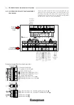
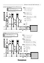
Page 36: ...e Assembly of a boiler with connection to two direct zones dhw production 9 10 external probe 6 7 storage tank probe 4 Pump heat circ 1 5 Pump heat circ 2 6 Storage tank pump 5 Storage tank recirculat...

Page 37: ...Assembly of a boiler with connection to one mixed zone and one direct zone dhw production 1 Mixing valve heat circ 1 OPEN 2 Mixing valve heat circ 1 CLOSED 5 Storage tank recirculation pump 7 Mixing...

Page 38: ...rc R isc 2 Pompa circ Risc 2 Miscelat rice Risc 2 Pompa ricircolo Pompa bollitore Sonda bollitore 23 0 V L1 N Aper tu ra Ch iusu ra B II TGC 4 5 F5 I A1 A2 A3 A4 A5 6 7 8 4 5 1 2 Instructions for the...

Page 39: ...e Sonda bollitore Sonda solare Pt1000 Pompa circuito solare COLLEGAMENTO SEZIONE E pannelli solari 3 4 5 A10 A11 IV TGC Instructions for the installer Connections to solar systems require changing a n...

Page 40: ...Terminal board on the boiler panel KF boiler probe External probe Terminal board on the boiler panel External Cascade Manager Pos 2 Pos 2 Pos 0 Pos 0 POS I POS I Flow switch Gas electrovalve Gas elec...

Page 41: ...valve positioned as indicated in the figure of parag 2 2 This valve must never be used to empty the system since all of the dirt contained in the system may accumulate in the boiler jeopardising smoot...

Page 42: ...the gas valve ATTENTION Remove cap 2 attach the red cap 3 to the flue point 1 Place the CO2 analysis probe 4 in the hole on the cap Once the measurement has been made take the cap out and use the rela...

Page 43: ...screw limit switch limits A Adjustment at maximum power Unscrew the closing cap for flue exhaust analysis point Place the analyser probe inside the flue analysis point Make burner 1 operate at max po...

Page 44: ...f the boiler does not start up again follow the operations described above until the boiler does start up again At this point adjust the burner as previously illustrated NOZZLES PRESSURES Frequently c...

Page 45: ...to be noted down in the control unit handbook All of the boiler modules are on and operating at MAXIMUM power All of the boiler modules are on and operating at MINIMUM power Fig 1 Fig 2 Turn clockwise...

Page 46: ...ater pressure gauge optional E TGC Control panel F TLG General Limit Thermostat trigger light G Fuses 1 6 3 A 2 10 A H Main Switch I When TLG General Limit Thermostat comes on it cuts off power to the...

Page 47: ...pen there are no gas leaks the external main switch is engaged the system safety valve on the boiler responds to operation and is connected to the sewer drain the condensate drain trap is filled with...

Page 48: ...is required to determine the effective state of an appliance and compare it with the optimal state This is carried out through measuring checking observing Maintenance is required to eliminate any de...

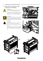
Page 49: ...oiler does not need to be cleaned The operation must therefore be limited to cleaning the trap ATTENTION A drop in the heat load can be caused by an obstruction in the exhaust channel or air intake pi...

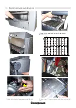
Page 50: ...ons and maintenance Unhook the fan chamber clamping spring right left side Take out screws A from each element with 13mm socket and flat key Take out the red silicone pipes and then the fan chamber El...

Page 51: ...nce Take out the gas fittings from the gas manifold with a 36 mm flat key Lift the rear burner block slightly and take out 2 pins with a 5 mm hex key until you reach holes C left and right side Lift t...

Page 52: ...obstructed clean if necessary Inspect the exhaust evacuation pipe and the flue Third phase Reassembly Once the body and or burners have been cleaned put the burners back in their places Put the new gr...

Page 53: ...53...

Page 54: ...54...

Page 55: ...55...

Page 56: ...mmergas com Immergas S p A 42041 Brescello RE Italy Tel 0522 689011 Fax 0522 680617 Certified company ISO 9001 This instruction booklet is made of ecological paper Cod 1 039293ENG rev ST 002264 002 02...

Reviews: