36
Filtro
Pompa
Collettore
Circuito di
riscaldamento 1
INAIL
VF
1
VF
VF
AF
Sonda
Ester na
Separator e
idraulico
1
2
3
Y4
4
GCI
1-2
*
Filtro
Po mpa
Collettore
Circuito di
riscaldamento 1
INAIL
F Ric.
C
VF
Circuito di
riscaldamento 2
VF
SPF
1
2
n
4
VF
VF
VF
AF
Sonda
Ester na
Separatore
idraulico
3
*
**
Instructions for the installer
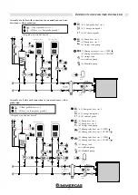
3.21 EXAMPLES OF INSTALLATION
(FUNCTIONAL DIAGRAM AND
DESCRIPTION OF CONNECTIONS)
Assembly of a boiler with connection
to a direct zone.
Assembly of a boiler with connection to two direct zones + dhw
production.
(9-10) external probe
(6-7) storage tank probe
(4) Pump heat. circ. 1
(5) Pump heat. circ. 2
(6) Storage tank pump
(5) Storage tank recirculation pump
(4-5) flow probe heat. circ. 2
(9-10) external probe
(4) Pump heat. circ. 1
(4) Manifold pump
(4) Manifold pump
(1) flow probe heat. circ. 1
(10) flow probe ground heat. circ. 1
* this probe can also not be used
(1) flow probe heat. circ. 1
(10) flow probe ground heat. circ. 1
* this probe can also not be used
Heating circuit 1
Heating circuit 2
Hydraulic
separator
Manifold
pump
External
Probe
Filter
Rec.
Heating circuit 1
Hydraulic
separator
Manifold
pump
External
Probe
Filter


