46
C B
GCI
D
E
F
G
H
I
A
L
1
2
Instructions for the installer
3.25 EMERGENCY AND SAFETY
OPERATIONS
GCI
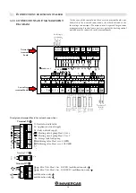
The GCI board allows you to avoid stopping the system if the main
management system of the control unit is out of order.
A YELLOW LED = flashing (communication between SDE and GCI) ok
GREEN LED = on (Pump On)
RED LED = on (Error Code detected)
B This allows you to re-arm the burners anytime they do not respond
to controls
C In position I the control unit operates on request at "SETPOINT
COSTANTE" ("CONSTANT SETPOINT"): 70°C. maximum power
50%
D Water pressure gauge (optional)
E TGC Control panel
F TLG General Limit Thermostat trigger light
G Fuses:
1 = 6.3 A
2 = 10 A
H Main Switch
I When TLG General Limit Thermostat comes on it cuts off power
to the boiler and light F comes on. To re-arm it, take off the cap and
press.
L Parallel series selector:
0 = Emergency on or control managed by PLC or BMS
I = Do not use
II = Parallel (service position for extensive diagnosis).
NOTE: the devices are positioned under the casing
next to the control unit.
NOTE: the emergency function only switches the
burners on in the boiler to 50% and 70°C in flow. All
system loads, including the manifold pump, must be
controlled manually.
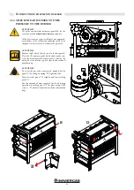
Condensate level sensor position (condensate collection pan
at the front of the boiler).


