By default, the subfolder “Preset” is
selected which was automatically created
during program installation. The file exten-
sion *.swc is automatically appended to the
file name entered.
Note: Only the switching statuses are saved and
not the numbers of the combination, i. e. the switch-
ing statuses saved can later be loaded into another
switch preset.
6.12.4 Loading a switching combination
from a computer
1) Use the buttons
–
to select the switching
combination for which saved switching sta-
tuses are to be loaded from the computer.
2) Click the button “Load from PC”. The dialog
window “Open” is displayed.
3) Select the file desired and then confirm your
selection.
The switching outputs will adopt the switching
statuses saved in the file.
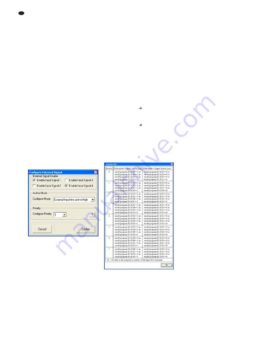
6.13 Switching inputs
The four extra configurations saved on the unit
may be retrieved via external switching signals.
In addition, different priorities can be assigned to
the switching inputs.
1) To configure the switching inputs, click the
button “Configure” located on the right-hand
side of the window (under “Extra Program”).
The dialog window “Configure External Sig-
nal” (fig. 27) is displayed.
2) After the settings described in chapters
6.13.1 to 6.13.3 have been made, click the
button “Confirm” to confirm your changes.
3) In the dialog window “Configure – Are you
sure?”, confirm or cancel the procedure.
6.13.1 Enabling or disabling inputs
Under “External Signal Enable”, select the
switching signals that are to be enabled for
switching over the connections INPUT PORT
(13). A tick in the box indicates that the corre-
sponding input will be included in the switchover
procedure.
6.13.2 Selecting the logic type (high / low)
Under “Active Mode”, define if the switchover is
to be triggered by high level [“External Input line
active High” (+5 V)] or low level [“External Input
line active Low” (0 V)].
6.13.3 Selecting priorities
Under “Priority”, select the priority to be used for
the switching inputs during switchover. Click the
button “?” to call up a table (fig. 28) providing
information on the actual meaning of the number
entered in the field “Configure Priority”. For each
number, the table lists, in descending order, the
priorities that are assigned to the individual
inputs.
Example:
All inputs have been enabled for switchover. The logic
type is “active High” and the value in the field “Config-
ure Priority” has been set to 3, i. e., according to the
table, the order of the inputs is S1, S4, S3, S2. This
means:
If switching input 1 is on high level (+5 V are present
between terminal “S1” and
), the 1
st
extra configura-
tion will be retrieved (consequently, the other inputs will
be of no relevance).
If switching input 1 is on low level (0 V are present
between terminal “S1” and
) and if switching input 4
is on high level, the 4
th
extra configuration will be
retrieved.
If the switching inputs 1 and 4 are on low level and if
switching input 3 is on high level, the 3
rd
extra configu-
ration will be retrieved.
If switching inputs 1, 3 and 4 are on low level and if
switching input 2 is on high level, the 2
nd
extra configu-
ration will be retrieved.
6.14 Selecting the interface mode
Similar to the procedure in the system menu, it is
possible to define if one of the interfaces USB or
RS 485 is to be set manually or to be recognized
automatically by the unit.
1) In the configuration window, under “USB/
RS 485”, click the button “Setup”. The dialog
window “USB/ RS 485 Setup” is displayed.
2) From the list field, define if the switchover is
to be performed automatically (“USB/ RS 485
Automatic”) or if the USB or RS-485 interface
most recently set by means of the system
menu (
chapter 5.3.2) is to be used (“USB/
RS 485 Manual”).
3) Click “OK” to confirm your selection or click
“Cancel” to cancel it.
6.15 Exiting a configuration window
To exit a configuration window, click the button
⊠
located in the upper right corner. Then con-
firm the confirmation message.
㉘
Window “Priority info”
㉗
Window “Configure External Signal”
26
GB


